

174
4 – Electrode reactions
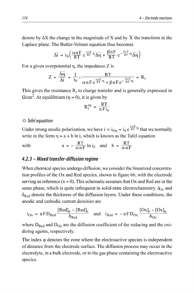
denote by ΔX the change in the magnitude of X and by X the transform in the
Laplace plane. The Butler-Volmer equation thus becomes
i i RT
nF
e
RT
nF e
0
RT
n F
RT
n F
α
η
β
η
Δ
Δ
Δ
=
+
η
η
−
a
b
c
m
For a given overpotential η, the impedance Z is
Z
i
i
1
n F e
nF e
RT
R
0
t
RT
n F
RT
n F
η
α
β
Δ
Δ
=
=
+
=
η
η
−
#
a
b
This gives the resistance R t to charge transfer and is generally expressed in
Ω cm
2
. At equilibrium (η = 0), it is given by
R
n Fi
RT
t
eq
0
=
L Tafel equation
Under strong anodic polarization, we have i i
i e
Ox
0
RT
n F
.
=
η
a
that we normally
write in the form η = a + b ln i, which is known as the Tafel equation
with
a
n F
RT
ln i and b
n F
RT
0
α
α
= −
=
4.2.3 – Mixed transfer-diffusion regime
When chemical species undergo diffusion, we consider the linearized concentration profiles of the Ox and Red species, shown in figure 66, with the electrode
serving as reference (x = 0). This schematic assumes that Ox and Red are in the
same phase, which is quite infrequent in solid-state electrochemistry. δ Ox and
δ Red denote the thickness of the diffusion layers. Under these conditions, the
anodic and cathodic current densities are
i
nFD
[Red] [Red] and i
n FD
[Ox] [Ox]
Ox
Red
Red
e
Red
O x
Ox
e
δ
δ
=
−
= −
−
ϕ
ϕ
where D Red and D Ox are the diffusion coefficient of the reducing and the oxidizing agents, respectively.
The index φ denotes the zone where the electroactive species is independent
of distance from the electrode surface. The diffusion process may occur in the
electrolyte, in a bulk electrode, or in the gas phase containing the electroactive
species.
4 – Electrode reactions
denote by ΔX the change in the magnitude of X and by X the transform in the
Laplace plane. The Butler-Volmer equation thus becomes
i i RT
nF
e
RT
nF e
0
RT
n F
RT
n F
α
η
β
η
Δ
Δ
Δ
=
+
η
η
−
a
b
c
m
For a given overpotential η, the impedance Z is
Z
i
i
1
n F e
nF e
RT
R
0
t
RT
n F
RT
n F
η
α
β
Δ
Δ
=
=
+
=
η
η
−
#
a
b
This gives the resistance R t to charge transfer and is generally expressed in
Ω cm
2
. At equilibrium (η = 0), it is given by
R
n Fi
RT
t
eq
0
=
L Tafel equation
Under strong anodic polarization, we have i i
i e
Ox
0
RT
n F
.
=
η
a
that we normally
write in the form η = a + b ln i, which is known as the Tafel equation
with
a
n F
RT
ln i and b
n F
RT
0
α
α
= −
=
4.2.3 – Mixed transfer-diffusion regime
When chemical species undergo diffusion, we consider the linearized concentration profiles of the Ox and Red species, shown in figure 66, with the electrode
serving as reference (x = 0). This schematic assumes that Ox and Red are in the
same phase, which is quite infrequent in solid-state electrochemistry. δ Ox and
δ Red denote the thickness of the diffusion layers. Under these conditions, the
anodic and cathodic current densities are
i
nFD
[Red] [Red] and i
n FD
[Ox] [Ox]
Ox
Red
Red
e
Red
O x
Ox
e
δ
δ
=
−
= −
−
ϕ
ϕ
where D Red and D Ox are the diffusion coefficient of the reducing and the oxidizing agents, respectively.
The index φ denotes the zone where the electroactive species is independent
of distance from the electrode surface. The diffusion process may occur in the
electrolyte, in a bulk electrode, or in the gas phase containing the electroactive
species.