

148
3 – Transport in ionic solids
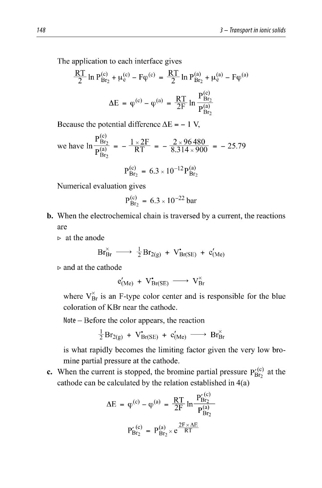
The application to each interface gives
2
RT
ln P
F
2
RT
ln P
F
Br
(c)
e
(c)
(c)
Br
(a)
e
(a)
(a)
2
2
μ
ϕ
μ
ϕ
+
−
=
+
−
E
2F
RT
ln P
P
(c)
(a)
Br
(a)
Br
(c)
2
2
ϕ
ϕ
Δ =
−
=
Because the potential difference ΔE = − 1 V,
we have
.
.
ln P
P
RT
F
1 2
8 314 900
2 96 480
25 79
( )
( )
Br
a
Br
c
2
2 = −
= −
= −
#
#
#
.
P
P
6 3 10
( )
( )
Br
c
Br
a
12
–
2
2
#
=
Numerical evaluation gives
.
P
b ar
6 3 10
( )
Br
c
22
2
#
=
−
b. When the electrochemical chain is traversed by a current, the reactions
are
2 at the anode
Br
#
Br $ 2
1
Br 2(g) + V
•
Br(SE) + e ′
(Me)
2 and at the cathode
e ′
(Me) + V
•
Br(SE) $ V
#
Br
where V
#
Br is an F-type color center and is responsible for the blue
coloration of KBr near the cathode.
Note – Before the color appears, the reaction
2
1
Br 2(g) + V
•
Br(SE) + e ′
(Me) $ Br
#
Br
is what rapidly becomes the limiting factor given the very low bromine partial pressure at the cathode.
c. When the current is stopped, the bromine partial pressure
( )
c
P Br 2
l at the
cathode can be calculated by the relation established in 4(a)
(c)
E
2F
RT
ln P
(c)
(a)
Br
(a)
Br
2
2
ϕ
ϕ
Δ =
−
=
Pl
(c)
P
e
Br
Br
(a)
RT
2F E
2
2
=
Δ
#
#
Pl
3 – Transport in ionic solids
The application to each interface gives
2
RT
ln P
F
2
RT
ln P
F
Br
(c)
e
(c)
(c)
Br
(a)
e
(a)
(a)
2
2
μ
ϕ
μ
ϕ
+
−
=
+
−
E
2F
RT
ln P
P
(c)
(a)
Br
(a)
Br
(c)
2
2
ϕ
ϕ
Δ =
−
=
Because the potential difference ΔE = − 1 V,
we have
.
.
ln P
P
RT
F
1 2
8 314 900
2 96 480
25 79
( )
( )
Br
a
Br
c
2
2 = −
= −
= −
#
#
#
.
P
P
6 3 10
( )
( )
Br
c
Br
a
12
–
2
2
#
=
Numerical evaluation gives
.
P
b ar
6 3 10
( )
Br
c
22
2
#
=
−
b. When the electrochemical chain is traversed by a current, the reactions
are
2 at the anode
Br
#
Br $ 2
1
Br 2(g) + V
•
Br(SE) + e ′
(Me)
2 and at the cathode
e ′
(Me) + V
•
Br(SE) $ V
#
Br
where V
#
Br is an F-type color center and is responsible for the blue
coloration of KBr near the cathode.
Note – Before the color appears, the reaction
2
1
Br 2(g) + V
•
Br(SE) + e ′
(Me) $ Br
#
Br
is what rapidly becomes the limiting factor given the very low bromine partial pressure at the cathode.
c. When the current is stopped, the bromine partial pressure
( )
c
P Br 2
l at the
cathode can be calculated by the relation established in 4(a)
(c)
E
2F
RT
ln P
(c)
(a)
Br
(a)
Br
2
2
ϕ
ϕ
Δ =
−
=
Pl
(c)
P
e
Br
Br
(a)
RT
2F E
2
2
=
Δ
#
#
Pl