

230
Chapter 3. Wave optics
–
–
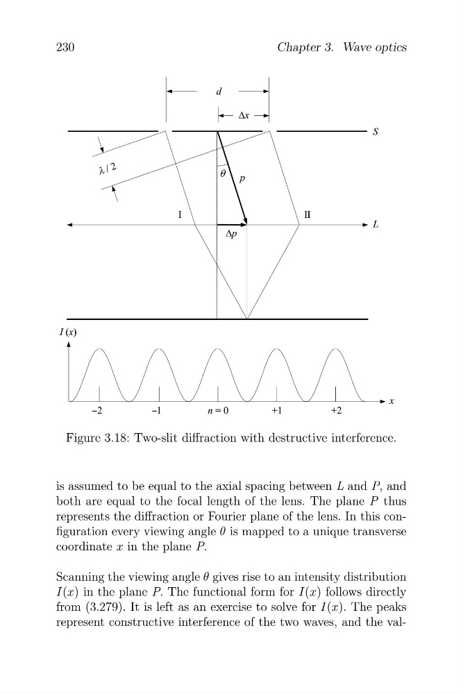
Figure 3.18: Two-slit diffraction with destructive interference.
is assumed to be equal to the axial spacing between L and P, and
both are equal to the focal length of the lens. The plane P thus
represents the diffraction or Fourier plane of the lens. In this configuration every viewing angle θ is mapped to a unique transverse
coordinate x in the plane P.
Scanning the viewing angle θ gives rise to an intensity distribution
I(x) in the plane P. The functional form for I(x) follows directly
from (3.279). It is left as an exercise to solve for I(x). The peaks
represent constructive interference of the two waves, and the val
Chapter 3. Wave optics
–
–
Figure 3.18: Two-slit diffraction with destructive interference.
is assumed to be equal to the axial spacing between L and P, and
both are equal to the focal length of the lens. The plane P thus
represents the diffraction or Fourier plane of the lens. In this configuration every viewing angle θ is mapped to a unique transverse
coordinate x in the plane P.
Scanning the viewing angle θ gives rise to an intensity distribution
I(x) in the plane P. The functional form for I(x) follows directly
from (3.279). It is left as an exercise to solve for I(x). The peaks
represent constructive interference of the two waves, and the val