

6
Introduction: The optical nature of a charged particle beam
the total beam current. A second aperture at +600 volts forms
an extraction field for emission. Finally, a high voltage electrode
at +18,000 volts is located far to the right, out of the figure. The
apertures both have diameter 0.6 mm, and the other dimensions
in the figure scale proportionally. The curved equipotentials penetrate the space occupied by the beam, and are separated by 100
volts in the figure. These equipotentials can be regarded as forming a lens, which focuses the beam to a crossover at the right of
the figure. Such an arrangement is used in a cathode ray tube.
The electrostatic equipotential surfaces and the electron trajectories are generated in a computer simulation by MEBS, Ltd. [63].
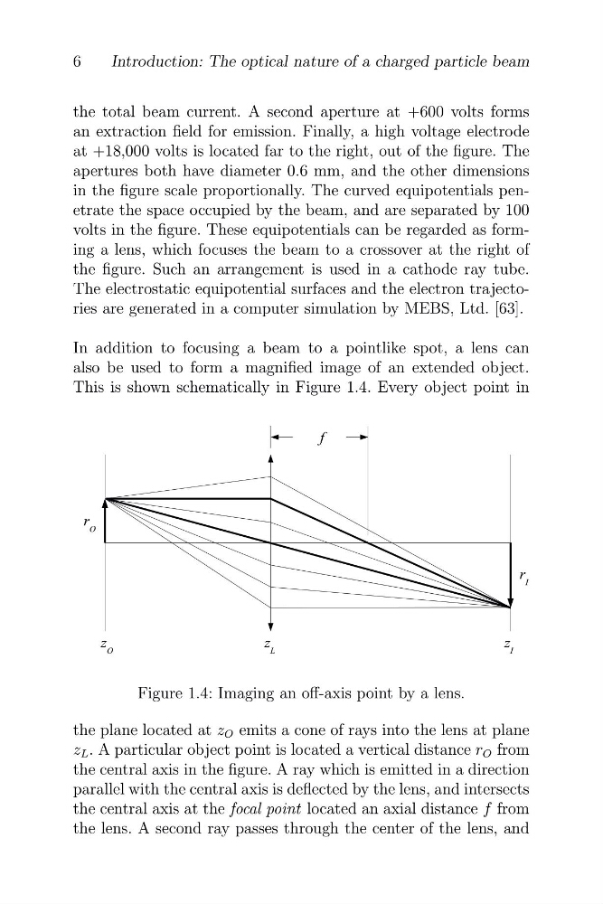
In addition to focusing a beam to a pointlike spot, a lens can
also be used to form a magnified image of an extended object.
This is shown schematically in Figure 1.4. Every object point in
Figure 1.4: Imaging an off-axis point by a lens.
the plane located at z O emits a cone of rays into the lens at plane
z L . A particular object point is located a vertical distance r O from
the central axis in the figure. A ray which is emitted in a direction
parallel with the central axis is deflected by the lens, and intersects
the central axis at the focal point located an axial distance f from
the lens. A second ray passes through the center of the lens, and
Introduction: The optical nature of a charged particle beam
the total beam current. A second aperture at +600 volts forms
an extraction field for emission. Finally, a high voltage electrode
at +18,000 volts is located far to the right, out of the figure. The
apertures both have diameter 0.6 mm, and the other dimensions
in the figure scale proportionally. The curved equipotentials penetrate the space occupied by the beam, and are separated by 100
volts in the figure. These equipotentials can be regarded as forming a lens, which focuses the beam to a crossover at the right of
the figure. Such an arrangement is used in a cathode ray tube.
The electrostatic equipotential surfaces and the electron trajectories are generated in a computer simulation by MEBS, Ltd. [63].
In addition to focusing a beam to a pointlike spot, a lens can
also be used to form a magnified image of an extended object.
This is shown schematically in Figure 1.4. Every object point in
Figure 1.4: Imaging an off-axis point by a lens.
the plane located at z O emits a cone of rays into the lens at plane
z L . A particular object point is located a vertical distance r O from
the central axis in the figure. A ray which is emitted in a direction
parallel with the central axis is deflected by the lens, and intersects
the central axis at the focal point located an axial distance f from
the lens. A second ray passes through the center of the lens, and