

Advances in Terahertz Imaging
155
movement of the sample can be avoided by using 2D arrays for faster image acquisition. Again, it is to be kept in mind that for a sample having multiple layers, multiple
reflections occur with THz imaging technique. Hence, some manual intervention
is also required to identify the temporal intervals which occur due to the distinct
reflected echoes. However, in order to get rid of human intervention, mechanisms
involving artificial intelligence can be developed.
3.4 THz Computed Tomography
Of late 3D imaging technology is becoming a field of active research. For THz imaging, it opens up a new possibility, as many materials happen to be quite transparent to
THz waves. Owing to this, the internal structure of a material can be revealed by 3D
THz imaging technique like THz computed tomography (THz-CT). The technique
is similar to the X-ray CT which is often used in the biomedical applications.
A set-up for THz-CT is considered. It is assumed that the THz beam incident onto
a sample is parallel in mature and is suffering from local optical losses which may be
considered to be distributed following f (x, y). An auxiliary function is defined as
g(x, y) = − f (x, y). Here, (x, y) are the coordinates in the local coordinate system
which is associated with the sample. A rotational stage rotated by an instantaneous
angle θ is considered on which a sample is placed. Then, with the sample rotation,
the detector moves by distance d along a fixed line. In this procedure, a sinogram
P(θ, t) is constructed. Here, the sinogram physically shows some measure of the
cumulative optical loss which occurs as because of transmission through the sample
along a certain straight line L(θ, t) defined by the detector position and the stage
rotation angle [61]:
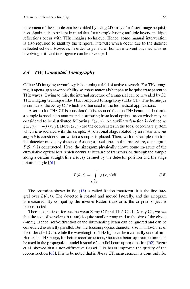
P(θ, t) =
L(θ,t)
g(x, y)dl
(18)
The operation shown in Eq. (18) is called Radon transform. It is the line integral over L(θ, t). The detector is rotated and moved laterally, and the sinogram
is measured. By computing the inverse Radon transform, the original object is
reconstructed.
There is a basic difference between X-ray CT and THZ-CT. In X-ray CT, we see
that the size of wavelength (~nm) is quite smaller compared to the size of the object
(~mm). Hence, self-diffraction of the illuminating beam can be ignored and can be
considered as strictly parallel. But the focusing optics diameter size in THz-CT is of
the order of ~10 cm, while the wavelength of THz light can be maximally several mm.
Hence, in THz range, for better reconstructions, Gaussian beam approximation is to
be used in the propagation model instead of parallel beam approximation [62]. Recur
et al. showed that a non-diffractive Bessel THz beam improved the quality of the
reconstruction [63]. It is to be noted that in X-ray CT, measurement is done only for
155
movement of the sample can be avoided by using 2D arrays for faster image acquisition. Again, it is to be kept in mind that for a sample having multiple layers, multiple
reflections occur with THz imaging technique. Hence, some manual intervention
is also required to identify the temporal intervals which occur due to the distinct
reflected echoes. However, in order to get rid of human intervention, mechanisms
involving artificial intelligence can be developed.
3.4 THz Computed Tomography
Of late 3D imaging technology is becoming a field of active research. For THz imaging, it opens up a new possibility, as many materials happen to be quite transparent to
THz waves. Owing to this, the internal structure of a material can be revealed by 3D
THz imaging technique like THz computed tomography (THz-CT). The technique
is similar to the X-ray CT which is often used in the biomedical applications.
A set-up for THz-CT is considered. It is assumed that the THz beam incident onto
a sample is parallel in mature and is suffering from local optical losses which may be
considered to be distributed following f (x, y). An auxiliary function is defined as
g(x, y) = − f (x, y). Here, (x, y) are the coordinates in the local coordinate system
which is associated with the sample. A rotational stage rotated by an instantaneous
angle θ is considered on which a sample is placed. Then, with the sample rotation,
the detector moves by distance d along a fixed line. In this procedure, a sinogram
P(θ, t) is constructed. Here, the sinogram physically shows some measure of the
cumulative optical loss which occurs as because of transmission through the sample
along a certain straight line L(θ, t) defined by the detector position and the stage
rotation angle [61]:
P(θ, t) =
L(θ,t)
g(x, y)dl
(18)
The operation shown in Eq. (18) is called Radon transform. It is the line integral over L(θ, t). The detector is rotated and moved laterally, and the sinogram
is measured. By computing the inverse Radon transform, the original object is
reconstructed.
There is a basic difference between X-ray CT and THZ-CT. In X-ray CT, we see
that the size of wavelength (~nm) is quite smaller compared to the size of the object
(~mm). Hence, self-diffraction of the illuminating beam can be ignored and can be
considered as strictly parallel. But the focusing optics diameter size in THz-CT is of
the order of ~10 cm, while the wavelength of THz light can be maximally several mm.
Hence, in THz range, for better reconstructions, Gaussian beam approximation is to
be used in the propagation model instead of parallel beam approximation [62]. Recur
et al. showed that a non-diffractive Bessel THz beam improved the quality of the
reconstruction [63]. It is to be noted that in X-ray CT, measurement is done only for