

380
A. Shishido et al.
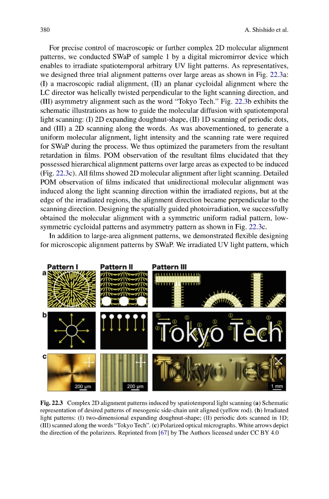
For precise control of macroscopic or further complex 2D molecular alignment
patterns, we conducted SWaP of sample 1 by a digital micromirror device which
enables to irradiate spatiotemporal arbitrary UV light patterns. As representatives,
we designed three trial alignment patterns over large areas as shown in Fig. 22.3a:
(I) a macroscopic radial alignment, (II) an planar cycloidal alignment where the
LC director was helically twisted perpendicular to the light scanning direction, and
(III) asymmetry alignment such as the word “Tokyo Tech.” Fig. 22.3b exhibits the
schematic illustrations as how to guide the molecular diffusion with spatiotemporal
light scanning: (I) 2D expanding doughnut-shape, (II) 1D scanning of periodic dots,
and (III) a 2D scanning along the words. As was abovementioned, to generate a
uniform molecular alignment, light intensity and the scanning rate were required
for SWaP during the process. We thus optimized the parameters from the resultant
retardation in films. POM observation of the resultant films elucidated that they
possessed hierarchical alignment patterns over large areas as expected to be induced
(Fig. 22.3c). All films showed 2D molecular alignment after light scanning. Detailed
POM observation of films indicated that unidirectional molecular alignment was
induced along the light scanning direction within the irradiated regions, but at the
edge of the irradiated regions, the alignment direction became perpendicular to the
scanning direction. Designing the spatially guided photoirradiation, we successfully
obtained the molecular alignment with a symmetric uniform radial pattern, lowsymmetric cycloidal patterns and asymmetry pattern as shown in Fig. 22.3c.
In addition to large-area alignment patterns, we demonstrated flexible designing
for microscopic alignment patterns by SWaP. We irradiated UV light pattern, which
Fig. 22.3 Complex 2D alignment patterns induced by spatiotemporal light scanning (a) Schematic
representation of desired patterns of mesogenic side-chain unit aligned (yellow rod). (b) Irradiated
light patterns: (I) two-dimensional expanding doughnut-shape; (II) periodic dots scanned in 1D;
(III) scanned along the words “Tokyo Tech”. (c) Polarized optical micrographs. White arrows depict
the direction of the polarizers. Reprinted from [67] by The Authors licensed under CC BY 4.0
A. Shishido et al.
For precise control of macroscopic or further complex 2D molecular alignment
patterns, we conducted SWaP of sample 1 by a digital micromirror device which
enables to irradiate spatiotemporal arbitrary UV light patterns. As representatives,
we designed three trial alignment patterns over large areas as shown in Fig. 22.3a:
(I) a macroscopic radial alignment, (II) an planar cycloidal alignment where the
LC director was helically twisted perpendicular to the light scanning direction, and
(III) asymmetry alignment such as the word “Tokyo Tech.” Fig. 22.3b exhibits the
schematic illustrations as how to guide the molecular diffusion with spatiotemporal
light scanning: (I) 2D expanding doughnut-shape, (II) 1D scanning of periodic dots,
and (III) a 2D scanning along the words. As was abovementioned, to generate a
uniform molecular alignment, light intensity and the scanning rate were required
for SWaP during the process. We thus optimized the parameters from the resultant
retardation in films. POM observation of the resultant films elucidated that they
possessed hierarchical alignment patterns over large areas as expected to be induced
(Fig. 22.3c). All films showed 2D molecular alignment after light scanning. Detailed
POM observation of films indicated that unidirectional molecular alignment was
induced along the light scanning direction within the irradiated regions, but at the
edge of the irradiated regions, the alignment direction became perpendicular to the
scanning direction. Designing the spatially guided photoirradiation, we successfully
obtained the molecular alignment with a symmetric uniform radial pattern, lowsymmetric cycloidal patterns and asymmetry pattern as shown in Fig. 22.3c.
In addition to large-area alignment patterns, we demonstrated flexible designing
for microscopic alignment patterns by SWaP. We irradiated UV light pattern, which
Fig. 22.3 Complex 2D alignment patterns induced by spatiotemporal light scanning (a) Schematic
representation of desired patterns of mesogenic side-chain unit aligned (yellow rod). (b) Irradiated
light patterns: (I) two-dimensional expanding doughnut-shape; (II) periodic dots scanned in 1D;
(III) scanned along the words “Tokyo Tech”. (c) Polarized optical micrographs. White arrows depict
the direction of the polarizers. Reprinted from [67] by The Authors licensed under CC BY 4.0