

1 Self-explaining Digital Systems
13
– the first cause—2 bits (4 bits in our implementation) for the sensor “push-button
(pb),” “microphone (mi),” or “light sensor (ls)” used to calculate the direction
according to the requirements,
– the second cause—8 bits for the reference to the unique tag for the triggering
event of the sensor module, and
– the third cause—8 bits for the reference to the unique tag for the triggering event
of the power module.
This totals to 20 bits; in our implementation we used 24 bits to conveniently
represent direction and sensors using hexadecimal digits. Explanations for the other
modules have different lengths depending on their needs.
1.4.2 Results
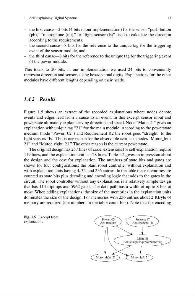
Figure 1.5 shows an extract of the recorded explanations where nodes denote
events and edges lead from a cause to an event. In this excerpt sensor input and
powerstate ultimately explain driving direction and speed. Node “Main: 21” gives an
explanation with unique tag “21” for the main module. According to the powerstate
medium (node “Power: 02”) and Requirement R2 the robot goes “straight” to the
light sensors “ls.” This is one reason for the observable actions in nodes “Motor_left:
21” and “Motor_right: 21.” The other reason is the current powerstate.
The original design has 257 lines of code, extensions for self-explanation require
119 lines, and the explanation unit has 28 lines. Table 1.2 gives an impression about
the design and the cost for explanation. The numbers of state bits and gates are
shown for four configurations: the plain robot controller without explanation and
with explanation units having 4, 32, and 256 entries. In the table these memories are
counted as state bits plus decoding and encoding logic that adds to the gates in the
circuit. The robot controller without any explanations is a relatively simple design
that has 113 flipflops and 5962 gates. The data path has a width of up to 8 bits at
most. When adding explanations, the size of the memories in the explanation units
dominates the size of the design. For memories with 256 entries about 2 KByte of
memory are required (the numbers in the table count bits). Note that the encoding
Fig. 1.5 Excerpt from
explanations
Main: 21
Act: straight ls,powerNotStrong
Motor_left: 21
Motor_right: 21
Power: 02
Act: medium
Sensors: 17
Act: changed: ls
13
– the first cause—2 bits (4 bits in our implementation) for the sensor “push-button
(pb),” “microphone (mi),” or “light sensor (ls)” used to calculate the direction
according to the requirements,
– the second cause—8 bits for the reference to the unique tag for the triggering
event of the sensor module, and
– the third cause—8 bits for the reference to the unique tag for the triggering event
of the power module.
This totals to 20 bits; in our implementation we used 24 bits to conveniently
represent direction and sensors using hexadecimal digits. Explanations for the other
modules have different lengths depending on their needs.
1.4.2 Results
Figure 1.5 shows an extract of the recorded explanations where nodes denote
events and edges lead from a cause to an event. In this excerpt sensor input and
powerstate ultimately explain driving direction and speed. Node “Main: 21” gives an
explanation with unique tag “21” for the main module. According to the powerstate
medium (node “Power: 02”) and Requirement R2 the robot goes “straight” to the
light sensors “ls.” This is one reason for the observable actions in nodes “Motor_left:
21” and “Motor_right: 21.” The other reason is the current powerstate.
The original design has 257 lines of code, extensions for self-explanation require
119 lines, and the explanation unit has 28 lines. Table 1.2 gives an impression about
the design and the cost for explanation. The numbers of state bits and gates are
shown for four configurations: the plain robot controller without explanation and
with explanation units having 4, 32, and 256 entries. In the table these memories are
counted as state bits plus decoding and encoding logic that adds to the gates in the
circuit. The robot controller without any explanations is a relatively simple design
that has 113 flipflops and 5962 gates. The data path has a width of up to 8 bits at
most. When adding explanations, the size of the memories in the explanation units
dominates the size of the design. For memories with 256 entries about 2 KByte of
memory are required (the numbers in the table count bits). Note that the encoding
Fig. 1.5 Excerpt from
explanations
Main: 21
Act: straight ls,powerNotStrong
Motor_left: 21
Motor_right: 21
Power: 02
Act: medium
Sensors: 17
Act: changed: ls