

186
H. Riener et al.
ESOP
synthesis
Reversible
logic.
synthesis
Mapping
(Cliff.+T)
Boolean
function
ESOP
form
Reverisble
circuit
Quantum
circuit
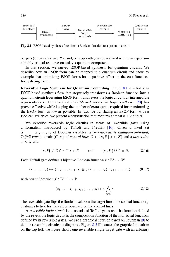
Fig. 8.1 ESOP-based synthesis flow from a Boolean function to a quantum circuit
outputs (often called ancillæ) and, consequently, can be realized with fewer qubits—
a highly critical resource on today’s quantum computers.
In this section, we survey ESOP-based synthesis for quantum circuits. We
describe how an ESOP form can be mapped to a quantum circuit and show by
example that optimizing ESOP forms has a positive effect on the cost functions
for realizing them.
Reversible Logic Synthesis for Quantum Computing Figure 8.1 illustrates an
ESOP-based synthesis flow that stepwisely transforms a Boolean function into a
quantum circuit leveraging ESOP forms and reversible logic circuits as intermediate
representations. The so-called ESOP-based reversible logic synthesis [20] has
proven effective while keeping the number of extra qubits required for transforming
the ESOP form as low as possible. In fact, for translating an ESOP form with n
Boolean variables, we present a construction that requires at most n + 2 qubits.
We describe reversible logic circuits in terms of reversible gates using
a formalism introduced by Toffoli and Fredkin [10]. Given a fixed set
X = x 1 , . . . , x n of Boolean variables, a (mixed-polarity multiple-controlled)
Toffoli gate is a pair (C, x t ) of control lines C ⊂ {x, ¯
x | x ∈ X} and a target line
x t ∈ X with
{x, ¯
x} ⊂ C for all x ∈ X
and
{x t , ¯
x t } ∪ C = ∅.
(8.16)
Each Toffoli gate defines a bijective Boolean function g : B n → B n
(x 1 , . . . , x n ) → (x 1 , . . . , x t−1 , x t ⊕ f (x 1 , . . . , x n ), x t+1 , . . . , x n ),
(8.17)
with control function f : B n−1 → B
(x 1 , . . . , x t−1 , x t+1 , . . . , x n ) →
c∈C
c.
(8.18)
The reversible gate flips the Boolean value on the target line if the control function f
evaluates to true for the values observed on the control lines.
A reversible logic circuit is a cascade of Toffoli gates and the function defined
by the reversible logic circuit is the composition function of the individual functions
defined by its reversible gates. We use a graphical notation based on Feynman [9] to
denote reversible circuits as diagrams. Figure 8.2 illustrates the graphical notation:
on the top-left, the figure shows one reversible single-target gate with an arbitrary
H. Riener et al.
ESOP
synthesis
Reversible
logic.
synthesis
Mapping
(Cliff.+T)
Boolean
function
ESOP
form
Reverisble
circuit
Quantum
circuit
Fig. 8.1 ESOP-based synthesis flow from a Boolean function to a quantum circuit
outputs (often called ancillæ) and, consequently, can be realized with fewer qubits—
a highly critical resource on today’s quantum computers.
In this section, we survey ESOP-based synthesis for quantum circuits. We
describe how an ESOP form can be mapped to a quantum circuit and show by
example that optimizing ESOP forms has a positive effect on the cost functions
for realizing them.
Reversible Logic Synthesis for Quantum Computing Figure 8.1 illustrates an
ESOP-based synthesis flow that stepwisely transforms a Boolean function into a
quantum circuit leveraging ESOP forms and reversible logic circuits as intermediate
representations. The so-called ESOP-based reversible logic synthesis [20] has
proven effective while keeping the number of extra qubits required for transforming
the ESOP form as low as possible. In fact, for translating an ESOP form with n
Boolean variables, we present a construction that requires at most n + 2 qubits.
We describe reversible logic circuits in terms of reversible gates using
a formalism introduced by Toffoli and Fredkin [10]. Given a fixed set
X = x 1 , . . . , x n of Boolean variables, a (mixed-polarity multiple-controlled)
Toffoli gate is a pair (C, x t ) of control lines C ⊂ {x, ¯
x | x ∈ X} and a target line
x t ∈ X with
{x, ¯
x} ⊂ C for all x ∈ X
and
{x t , ¯
x t } ∪ C = ∅.
(8.16)
Each Toffoli gate defines a bijective Boolean function g : B n → B n
(x 1 , . . . , x n ) → (x 1 , . . . , x t−1 , x t ⊕ f (x 1 , . . . , x n ), x t+1 , . . . , x n ),
(8.17)
with control function f : B n−1 → B
(x 1 , . . . , x t−1 , x t+1 , . . . , x n ) →
c∈C
c.
(8.18)
The reversible gate flips the Boolean value on the target line if the control function f
evaluates to true for the values observed on the control lines.
A reversible logic circuit is a cascade of Toffoli gates and the function defined
by the reversible logic circuit is the composition function of the individual functions
defined by its reversible gates. We use a graphical notation based on Feynman [9] to
denote reversible circuits as diagrams. Figure 8.2 illustrates the graphical notation:
on the top-left, the figure shows one reversible single-target gate with an arbitrary