

1 Self-explaining Digital Systems
11
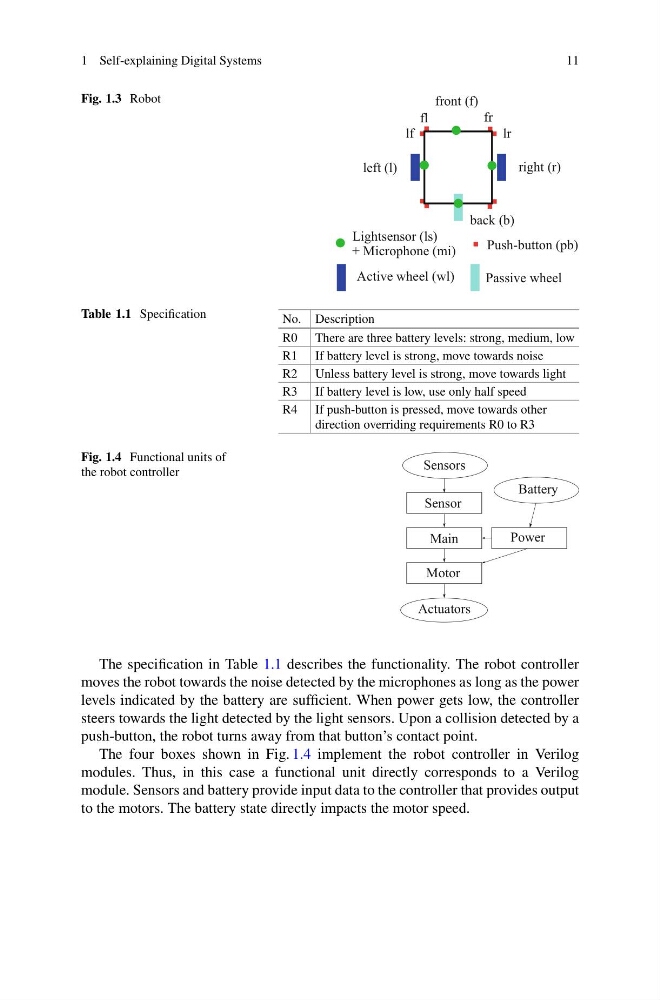
Fig. 1.3 Robot
Lightsensor (ls)
Active wheel (wl)
Passive wheel
Push-button (pb)
+ Microphone (mi)
left (l)
right (r)
front (f)
back (b)
fl
lf
fr
lr
Table 1.1 Specification
No. Description
R0 There are three battery levels: strong, medium, low
R1 If battery level is strong, move towards noise
R2 Unless battery level is strong, move towards light
R3 If battery level is low, use only half speed
R4 If push-button is pressed, move towards other
direction overriding requirements R0 to R3
Fig. 1.4 Functional units of
the robot controller
Main
Motor
Power
Actuators
Sensors
Sensor
Battery
The specification in Table 1.1 describes the functionality. The robot controller
moves the robot towards the noise detected by the microphones as long as the power
levels indicated by the battery are sufficient. When power gets low, the controller
steers towards the light detected by the light sensors. Upon a collision detected by a
push-button, the robot turns away from that button’s contact point.
The four boxes shown in Fig. 1.4 implement the robot controller in Verilog
modules. Thus, in this case a functional unit directly corresponds to a Verilog
module. Sensors and battery provide input data to the controller that provides output
to the motors. The battery state directly impacts the motor speed.
11
Fig. 1.3 Robot
Lightsensor (ls)
Active wheel (wl)
Passive wheel
Push-button (pb)
+ Microphone (mi)
left (l)
right (r)
front (f)
back (b)
fl
lf
fr
lr
Table 1.1 Specification
No. Description
R0 There are three battery levels: strong, medium, low
R1 If battery level is strong, move towards noise
R2 Unless battery level is strong, move towards light
R3 If battery level is low, use only half speed
R4 If push-button is pressed, move towards other
direction overriding requirements R0 to R3
Fig. 1.4 Functional units of
the robot controller
Main
Motor
Power
Actuators
Sensors
Sensor
Battery
The specification in Table 1.1 describes the functionality. The robot controller
moves the robot towards the noise detected by the microphones as long as the power
levels indicated by the battery are sufficient. When power gets low, the controller
steers towards the light detected by the light sensors. Upon a collision detected by a
push-button, the robot turns away from that button’s contact point.
The four boxes shown in Fig. 1.4 implement the robot controller in Verilog
modules. Thus, in this case a functional unit directly corresponds to a Verilog
module. Sensors and battery provide input data to the controller that provides output
to the motors. The battery state directly impacts the motor speed.