

164
A. Bernasconi et al.
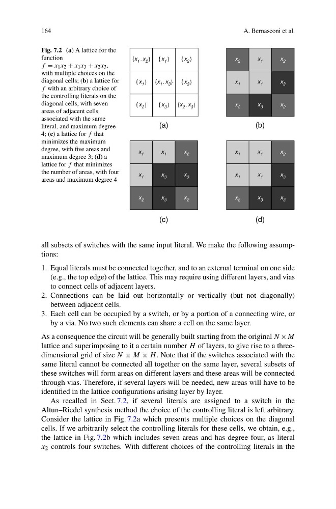
Fig. 7.2 (a) A lattice for the
function
f = x 1 x 2 + x 1 x 3 + x 2 x 3 ,
with multiple choices on the
diagonal cells; (b) a lattice for
f with an arbitrary choice of
the controlling literals on the
diagonal cells, with seven
areas of adjacent cells
associated with the same
literal, and maximum degree
4; (c) a lattice for f that
minimizes the maximum
degree, with five areas and
maximum degree 3; (d) a
lattice for f that minimizes
the number of areas, with four
areas and maximum degree 4
{x 1 , x 2 }
{ x 1 }
{ x 2 }
{x 1
, x 3 }
{ x 3 }
{ x 2 }
{ x 3 }
{x 2 , x 3 }
(c)
{ x 1 }
x 1
x 1
x 2
x 3
x 3
x 2
x 3
x 2
x 1
x 1
x 1
x 2
x 1
x 3
x 2
x 3
x 3
x 1
(d)
(a)
(b)
x 2
x 1
x 2
x 1
x 3
x 2
x 3
x 2
x 1
all subsets of switches with the same input literal. We make the following assumptions:
1. Equal literals must be connected together, and to an external terminal on one side
(e.g., the top edge) of the lattice. This may require using different layers, and vias
to connect cells of adjacent layers.
2. Connections can be laid out horizontally or vertically (but not diagonally)
between adjacent cells.
3. Each cell can be occupied by a switch, or by a portion of a connecting wire, or
by a via. No two such elements can share a cell on the same layer.
As a consequence the circuit will be generally built starting from the original N ×M
lattice and superimposing to it a certain number H of layers, to give rise to a threedimensional grid of size N × M × H . Note that if the switches associated with the
same literal cannot be connected all together on the same layer, several subsets of
these switches will form areas on different layers and these areas will be connected
through vias. Therefore, if several layers will be needed, new areas will have to be
identified in the lattice configurations arising layer by layer.
As recalled in Sect. 7.2, if several literals are assigned to a switch in the
Altun–Riedel synthesis method the choice of the controlling literal is left arbitrary.
Consider the lattice in Fig. 7.2a which presents multiple choices on the diagonal
cells. If we arbitrarily select the controlling literals for these cells, we obtain, e.g.,
the lattice in Fig. 7.2b which includes seven areas and has degree four, as literal
x 2 controls four switches. With different choices of the controlling literals in the
A. Bernasconi et al.
Fig. 7.2 (a) A lattice for the
function
f = x 1 x 2 + x 1 x 3 + x 2 x 3 ,
with multiple choices on the
diagonal cells; (b) a lattice for
f with an arbitrary choice of
the controlling literals on the
diagonal cells, with seven
areas of adjacent cells
associated with the same
literal, and maximum degree
4; (c) a lattice for f that
minimizes the maximum
degree, with five areas and
maximum degree 3; (d) a
lattice for f that minimizes
the number of areas, with four
areas and maximum degree 4
{x 1 , x 2 }
{ x 1 }
{ x 2 }
{x 1
, x 3 }
{ x 3 }
{ x 2 }
{ x 3 }
{x 2 , x 3 }
(c)
{ x 1 }
x 1
x 1
x 2
x 3
x 3
x 2
x 3
x 2
x 1
x 1
x 1
x 2
x 1
x 3
x 2
x 3
x 3
x 1
(d)
(a)
(b)
x 2
x 1
x 2
x 1
x 3
x 2
x 3
x 2
x 1
all subsets of switches with the same input literal. We make the following assumptions:
1. Equal literals must be connected together, and to an external terminal on one side
(e.g., the top edge) of the lattice. This may require using different layers, and vias
to connect cells of adjacent layers.
2. Connections can be laid out horizontally or vertically (but not diagonally)
between adjacent cells.
3. Each cell can be occupied by a switch, or by a portion of a connecting wire, or
by a via. No two such elements can share a cell on the same layer.
As a consequence the circuit will be generally built starting from the original N ×M
lattice and superimposing to it a certain number H of layers, to give rise to a threedimensional grid of size N × M × H . Note that if the switches associated with the
same literal cannot be connected all together on the same layer, several subsets of
these switches will form areas on different layers and these areas will be connected
through vias. Therefore, if several layers will be needed, new areas will have to be
identified in the lattice configurations arising layer by layer.
As recalled in Sect. 7.2, if several literals are assigned to a switch in the
Altun–Riedel synthesis method the choice of the controlling literal is left arbitrary.
Consider the lattice in Fig. 7.2a which presents multiple choices on the diagonal
cells. If we arbitrarily select the controlling literals for these cells, we obtain, e.g.,
the lattice in Fig. 7.2b which includes seven areas and has degree four, as literal
x 2 controls four switches. With different choices of the controlling literals in the