

38
Water for Energy and Fuel Production
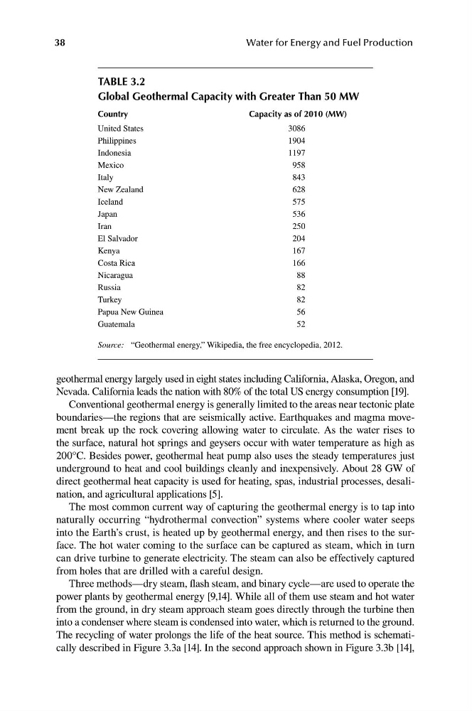
taBle 3.2
Global Geothermal Capacity with Greater than 50 mW
Country
Capacity as of 2010 (mW)
United States
3086
Philippines
1904
Indonesia
1197
Mexico
958
Italy
843
New Zealand
628
Iceland
575
Japan
536
Iran
250
El Salvador
204
Kenya
167
Costa Rica
166
Nicaragua
88
Russia
82
Turkey
82
Papua New Guinea
56
Guatemala
52
Source: “Geothermal energy,” Wikipedia, the free encyclopedia, 2012.
geothermal energy largely used in eight states including California, Alaska, Oregon, and
Nevada. California leads the nation with 80% of the total US energy consumption [19].
Conventional geothermal energy is generally limited to the areas near tectonic plate
boundaries—the regions that are seismically active. Earthquakes and magma movement break up the rock covering allowing water to circulate. As the water rises to
the surface, natural hot springs and geysers occur with water temperature as high as
200°C. Besides power, geothermal heat pump also uses the steady temperatures just
underground to heat and cool buildings cleanly and inexpensively. About 28 GW of
direct geothermal heat capacity is used for heating, spas, industrial processes, desalination, and agricultural applications [5].
The most common current way of capturing the geothermal energy is to tap into
naturally occurring “hydrothermal convection” systems where cooler water seeps
into the Earth’s crust, is heated up by geothermal energy, and then rises to the surface. The hot water coming to the surface can be captured as steam, which in turn
can drive turbine to generate electricity. The steam can also be effectively captured
from holes that are drilled with a careful design.
Three methods—dry steam, flash steam, and binary cycle—are used to operate the
power plants by geothermal energy [9,14]. While all of them use steam and hot water
from the ground, in dry steam approach steam goes directly through the turbine then
into a condenser where steam is condensed into water, which is returned to the ground.
The recycling of water prolongs the life of the heat source. This method is schematically described in Figure 3.3a [14]. In the second approach shown in Figure 3.3b [14],