

Gas to
compressor
Claystone
Claystone
Claystone
Coal
Casing
Tubing
Annulus
Cement
to surface
Water
Ground
level
Shallow water sand
Carbonaceous
shale
Carbonaceous
shale
Submersible
pump
Shallow
water
sand
Sump
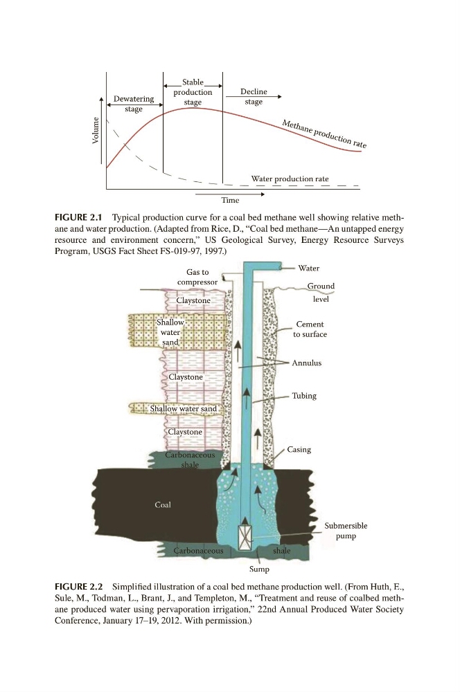
FIGURE 2.2 Simplified illustration of a coal bed methane production well. (From Huth, E.,
Sule, M., Todman, L., Brant, J., and Templeton, M., “Treatment and reuse of coalbed methane produced water using pervaporation irrigation,” 22nd Annual Produced Water Society
Conference, January 17–19, 2012. With permission.)
Dewatering
stage
Decline
stage
Water production rate
Time
M e th an e p ro d u ct io n ra te
Volume
Stable
production
stage
FIGURE 2.1 Typical production curve for a coal bed methane well showing relative methane and water production. (Adapted from Rice, D., “Coal bed methane—An untapped energy
resource and environment concern,” US Geological Survey, Energy Resource Surveys
Program, USGS Fact Sheet FS-019-97, 1997.)
compressor
Claystone
Claystone
Claystone
Coal
Casing
Tubing
Annulus
Cement
to surface
Water
Ground
level
Shallow water sand
Carbonaceous
shale
Carbonaceous
shale
Submersible
pump
Shallow
water
sand
Sump
FIGURE 2.2 Simplified illustration of a coal bed methane production well. (From Huth, E.,
Sule, M., Todman, L., Brant, J., and Templeton, M., “Treatment and reuse of coalbed methane produced water using pervaporation irrigation,” 22nd Annual Produced Water Society
Conference, January 17–19, 2012. With permission.)
Dewatering
stage
Decline
stage
Water production rate
Time
M e th an e p ro d u ct io n ra te
Volume
Stable
production
stage
FIGURE 2.1 Typical production curve for a coal bed methane well showing relative methane and water production. (Adapted from Rice, D., “Coal bed methane—An untapped energy
resource and environment concern,” US Geological Survey, Energy Resource Surveys
Program, USGS Fact Sheet FS-019-97, 1997.)