

Devolatilization and pyrolysis zone
(a)
Reducing zone
Combustion zone
200°C−550°C
Overburden
Gas blast in
Product gas out
Production well
Injection well
Coal seam
550°C−900°C
>900°C
25 m
25 m
25 m
Row 1
Row 2
Row 3
Row 4
Producing
gas
Linking
Drilling and
Air inlet
manifold
Product gas
manifold
25 m
Preparing
Row 5
Wells
(b)
97
Steam Gasification and Reforming Technologies
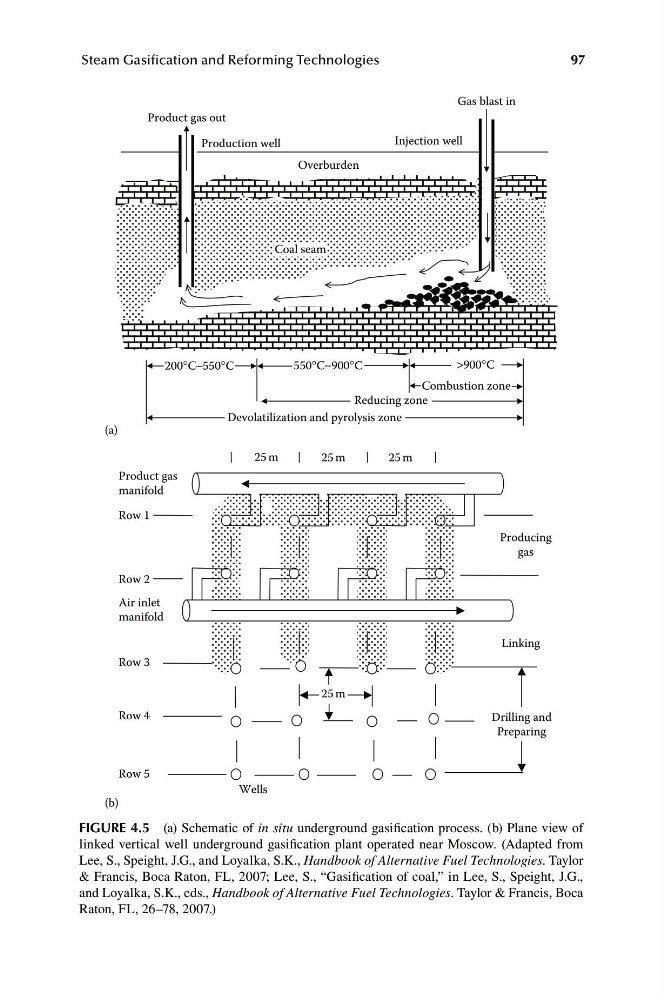
FiGUre 4.5 (a) Schematic of in situ underground gasification process. (b) Plane view of
linked vertical well underground gasification plant operated near Moscow. (Adapted from
Lee, S., Speight, J.G., and Loyalka, S.K., Handbook of Alternative Fuel Technologies. Taylor
& Francis, Boca Raton, FL, 2007; Lee, S., “Gasification of coal,” in Lee, S., Speight, J.G.,
and Loyalka, S.K., eds., Handbook of Alternative Fuel Technologies. Taylor & Francis, Boca
Raton, FL, 26–78, 2007.)
(a)
Reducing zone
Combustion zone
200°C−550°C
Overburden
Gas blast in
Product gas out
Production well
Injection well
Coal seam
550°C−900°C
>900°C
25 m
25 m
25 m
Row 1
Row 2
Row 3
Row 4
Producing
gas
Linking
Drilling and
Air inlet
manifold
Product gas
manifold
25 m
Preparing
Row 5
Wells
(b)
97
Steam Gasification and Reforming Technologies
FiGUre 4.5 (a) Schematic of in situ underground gasification process. (b) Plane view of
linked vertical well underground gasification plant operated near Moscow. (Adapted from
Lee, S., Speight, J.G., and Loyalka, S.K., Handbook of Alternative Fuel Technologies. Taylor
& Francis, Boca Raton, FL, 2007; Lee, S., “Gasification of coal,” in Lee, S., Speight, J.G.,
and Loyalka, S.K., eds., Handbook of Alternative Fuel Technologies. Taylor & Francis, Boca
Raton, FL, 26–78, 2007.)