

a : OR À ðab; cdÞ; AND þ ðbb; dcÞ
ð 12:1Þ
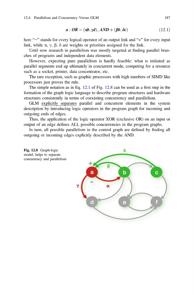
here “−” stands for every logical operator of an output link and “+” for every input
link, while a, c, b, d are weights or priorities assigned for the link.
Until now research in parallelism was mostly targeted at finding parallel branches of programs and independent data elements.
However, expecting pure parallelism is hardly feasible: what is initiated as
parallel segments end up ultimately in concurrent mode, competing for a resource
such as a socket, printer, data concentrator, etc.
The rare exception, such as graphic processors with high numbers of SIMD like
processors just proves the rule.
The simple notation as in Eq. 12.1 of Fig. 12.8 can be used as a first step in the
formation of the graph logic language to describe program structures and hardware
structures consistently in terms of coexisting concurrency and parallelism.
GLM explicitly separates parallel and concurrent elements in the system
description by introducing logic operators in the program graph for incoming and
outgoing ends of edges.
Thus, the application of the logic operator XOR (exclusive OR) on an input or
output of an edge defines ALL possible concurrencies in the program graphs.
In turn, all possible parallelism in the control graph are defined by finding all
outgoing or incoming edges explicitly described by the AND.
Fig. 12.8 Graph-logic
model, helps to separate
concurrency and parallelism
12.4 Parallelism and Concurrency Versus GLM
187
ð 12:1Þ
here “−” stands for every logical operator of an output link and “+” for every input
link, while a, c, b, d are weights or priorities assigned for the link.
Until now research in parallelism was mostly targeted at finding parallel branches of programs and independent data elements.
However, expecting pure parallelism is hardly feasible: what is initiated as
parallel segments end up ultimately in concurrent mode, competing for a resource
such as a socket, printer, data concentrator, etc.
The rare exception, such as graphic processors with high numbers of SIMD like
processors just proves the rule.
The simple notation as in Eq. 12.1 of Fig. 12.8 can be used as a first step in the
formation of the graph logic language to describe program structures and hardware
structures consistently in terms of coexisting concurrency and parallelism.
GLM explicitly separates parallel and concurrent elements in the system
description by introducing logic operators in the program graph for incoming and
outgoing ends of edges.
Thus, the application of the logic operator XOR (exclusive OR) on an input or
output of an edge defines ALL possible concurrencies in the program graphs.
In turn, all possible parallelism in the control graph are defined by finding all
outgoing or incoming edges explicitly described by the AND.
Fig. 12.8 Graph-logic
model, helps to separate
concurrency and parallelism
12.4 Parallelism and Concurrency Versus GLM
187