

In both variants, the software must check whether there is enough space free on
the stable storage. If not, additional space is freed by deleting (erasing) the oldest
recovery point entries on the stable storage. The same is done for the recovery point
index entries if no free space is left for an index.
Note that at least two erase pages are needed for the index, as the smallest entity
that can be erased is an erase block. The index size must be chosen according to the
recovery strategy, based on the expected recovery point size.
The recovery point entries are stored in a log-based way, and thus it is likely that
index entries pointing to already overwritten recovery points are present.
Whenever a recovery point is read, the software therefore validates the recovery
point by checking the fingerprint, the sequence number and the checksum over the
whole recovery point. This simple design guarantees equal distribution of writes
across the whole flash and therefore maximum mean time to failure.
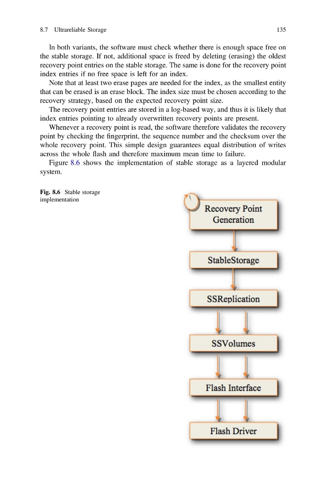
Figure 8.6 shows the implementation of stable storage as a layered modular
system.
Fig. 8.6 Stable storage
implementation
8.7 Ultrareliable Storage
135
the stable storage. If not, additional space is freed by deleting (erasing) the oldest
recovery point entries on the stable storage. The same is done for the recovery point
index entries if no free space is left for an index.
Note that at least two erase pages are needed for the index, as the smallest entity
that can be erased is an erase block. The index size must be chosen according to the
recovery strategy, based on the expected recovery point size.
The recovery point entries are stored in a log-based way, and thus it is likely that
index entries pointing to already overwritten recovery points are present.
Whenever a recovery point is read, the software therefore validates the recovery
point by checking the fingerprint, the sequence number and the checksum over the
whole recovery point. This simple design guarantees equal distribution of writes
across the whole flash and therefore maximum mean time to failure.
Figure 8.6 shows the implementation of stable storage as a layered modular
system.
Fig. 8.6 Stable storage
implementation
8.7 Ultrareliable Storage
135