

6.3 Geometrically Nonlinear Analysis of Smart Structures
119
(a)
0
50
100
0
50
100
0
5
10
15
Θ
1 (mm)
Θ
2 (mm)
| 1
| (degree)
(b)
0
50
100
0
50
100
0
5
10
15
Θ
1 (mm)
Θ
2 (mm)
| 2
| (degree)
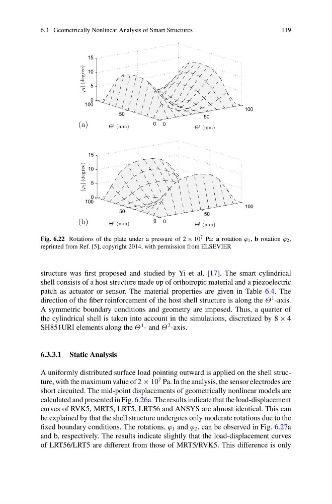
Fig. 6.22 Rotations of the plate under a pressure of 2 × 10 7 Pa: a rotation ϕ 1 , b rotation ϕ 2 ,
reprinted from Ref. [5], copyright 2014, with permission from ELSEVIER
structure was first proposed and studied by Yi et al. [17]. The smart cylindrical
shell consists of a host structure made up of orthotropic material and a piezoelectric
patch as actuator or sensor. The material properties are given in Table 6.4. The
direction of the fiber reinforcement of the host shell structure is along the Θ
1 -axis.
A symmetric boundary conditions and geometry are imposed. Thus, a quarter of
the cylindrical shell is taken into account in the simulations, discretized by 8 × 4
SH851URI elements along the Θ
1 - and Θ
2 -axis.
6.3.3.1 Static Analysis
A uniformly distributed surface load pointing outward is applied on the shell structure, with the maximum value of 2 × 10
7 Pa. In the analysis, the sensor electrodes are
short circuited. The mid-point displacements of geometrically nonlinear models are
calculated and presented in Fig. 6.26a. The results indicate that the load-displacement
curves of RVK5, MRT5, LRT5, LRT56 and ANSYS are almost identical. This can
be explained by that the shell structure undergoes only moderate rotations due to the
fixed boundary conditions. The rotations, ϕ 1 and ϕ 2 , can be observed in Fig. 6.27a
and b, respectively. The results indicate slightly that the load-displacement curves
of LRT56/LRT5 are different from those of MRT5/RVK5. This difference is only
119
(a)
0
50
100
0
50
100
0
5
10
15
Θ
1 (mm)
Θ
2 (mm)
| 1
| (degree)
(b)
0
50
100
0
50
100
0
5
10
15
Θ
1 (mm)
Θ
2 (mm)
| 2
| (degree)
Fig. 6.22 Rotations of the plate under a pressure of 2 × 10 7 Pa: a rotation ϕ 1 , b rotation ϕ 2 ,
reprinted from Ref. [5], copyright 2014, with permission from ELSEVIER
structure was first proposed and studied by Yi et al. [17]. The smart cylindrical
shell consists of a host structure made up of orthotropic material and a piezoelectric
patch as actuator or sensor. The material properties are given in Table 6.4. The
direction of the fiber reinforcement of the host shell structure is along the Θ
1 -axis.
A symmetric boundary conditions and geometry are imposed. Thus, a quarter of
the cylindrical shell is taken into account in the simulations, discretized by 8 × 4
SH851URI elements along the Θ
1 - and Θ
2 -axis.
6.3.3.1 Static Analysis
A uniformly distributed surface load pointing outward is applied on the shell structure, with the maximum value of 2 × 10
7 Pa. In the analysis, the sensor electrodes are
short circuited. The mid-point displacements of geometrically nonlinear models are
calculated and presented in Fig. 6.26a. The results indicate that the load-displacement
curves of RVK5, MRT5, LRT5, LRT56 and ANSYS are almost identical. This can
be explained by that the shell structure undergoes only moderate rotations due to the
fixed boundary conditions. The rotations, ϕ 1 and ϕ 2 , can be observed in Fig. 6.27a
and b, respectively. The results indicate slightly that the load-displacement curves
of LRT56/LRT5 are different from those of MRT5/RVK5. This difference is only