

112
6 Nonlinear Analysis of Piezoceramic Laminated Structures
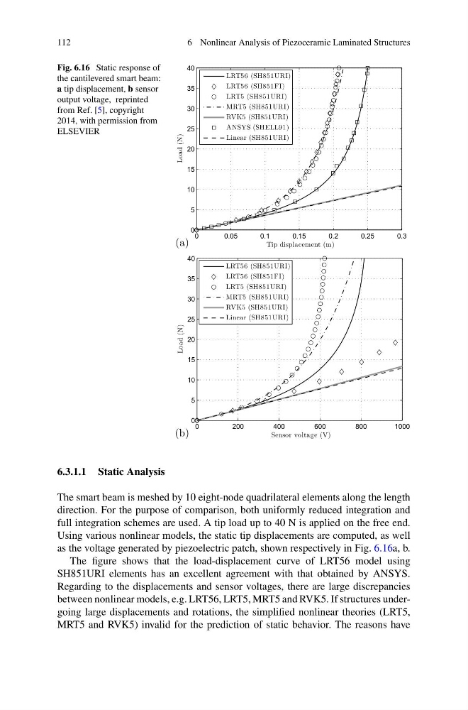
Fig. 6.16 Static response of
the cantilevered smart beam:
a tip displacement, b sensor
output voltage, reprinted
from Ref. [5], copyright
2014, with permission from
ELSEVIER
(a)
0
0.05
0.1
0.15
0.2
0.25
0.3
0
5
10
15
20
25
30
35
40
Tip displacement (m)
Load (N)
LRT56 (SH851URI)
LRT56 (SH851FI)
LRT5 (SH851URI)
MRT5 (SH851URI)
RVK5 (SH851URI)
ANSYS (SHELL91)
Linear (SH851URI)
(b)
0
200
400
600
800
1000
0
5
10
15
20
25
30
35
40
Sensor voltage (V)
Load (N)
LRT56 (SH851URI)
LRT56 (SH851FI)
LRT5 (SH851URI)
MRT5 (SH851URI)
RVK5 (SH851URI)
Linear (SH851URI)
6.3.1.1 Static Analysis
The smart beam is meshed by 10 eight-node quadrilateral elements along the length
direction. For the purpose of comparison, both uniformly reduced integration and
full integration schemes are used. A tip load up to 40 N is applied on the free end.
Using various nonlinear models, the static tip displacements are computed, as well
as the voltage generated by piezoelectric patch, shown respectively in Fig. 6.16a, b.
The figure shows that the load-displacement curve of LRT56 model using
SH851URI elements has an excellent agreement with that obtained by ANSYS.
Regarding to the displacements and sensor voltages, there are large discrepancies
between nonlinear models, e.g. LRT56, LRT5, MRT5 and RVK5. If structures undergoing large displacements and rotations, the simplified nonlinear theories (LRT5,
MRT5 and RVK5) invalid for the prediction of static behavior. The reasons have
6 Nonlinear Analysis of Piezoceramic Laminated Structures
Fig. 6.16 Static response of
the cantilevered smart beam:
a tip displacement, b sensor
output voltage, reprinted
from Ref. [5], copyright
2014, with permission from
ELSEVIER
(a)
0
0.05
0.1
0.15
0.2
0.25
0.3
0
5
10
15
20
25
30
35
40
Tip displacement (m)
Load (N)
LRT56 (SH851URI)
LRT56 (SH851FI)
LRT5 (SH851URI)
MRT5 (SH851URI)
RVK5 (SH851URI)
ANSYS (SHELL91)
Linear (SH851URI)
(b)
0
200
400
600
800
1000
0
5
10
15
20
25
30
35
40
Sensor voltage (V)
Load (N)
LRT56 (SH851URI)
LRT56 (SH851FI)
LRT5 (SH851URI)
MRT5 (SH851URI)
RVK5 (SH851URI)
Linear (SH851URI)
6.3.1.1 Static Analysis
The smart beam is meshed by 10 eight-node quadrilateral elements along the length
direction. For the purpose of comparison, both uniformly reduced integration and
full integration schemes are used. A tip load up to 40 N is applied on the free end.
Using various nonlinear models, the static tip displacements are computed, as well
as the voltage generated by piezoelectric patch, shown respectively in Fig. 6.16a, b.
The figure shows that the load-displacement curve of LRT56 model using
SH851URI elements has an excellent agreement with that obtained by ANSYS.
Regarding to the displacements and sensor voltages, there are large discrepancies
between nonlinear models, e.g. LRT56, LRT5, MRT5 and RVK5. If structures undergoing large displacements and rotations, the simplified nonlinear theories (LRT5,
MRT5 and RVK5) invalid for the prediction of static behavior. The reasons have