

110
6 Nonlinear Analysis of Piezoceramic Laminated Structures
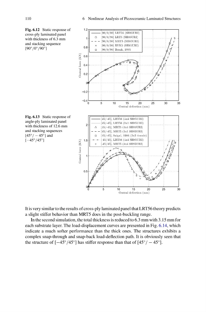
Fig. 6.12 Static response of
cross-ply laminated panel
with thickness of 6.3 mm
and stacking sequence
[90 ◦ /0 ◦ /90 ◦ ]
0
5
10
15
20
25
30
35
−0.4
−0.2
0
0.2
0.4
0.6
0.8
1
1.2
Central deflection (mm)
Central force (KN)
[90/0/90] LRT56 (SH85URI)
[90/0/90] LRT5 (SH85URI)
[90/0/90] MRT5 (SH85URI)
[90/0/90] RVK5 (SH85URI)
[90/0/90] Brank, 1995
Fig. 6.13 Static response of
angle-ply laminated panel
with thickness of 12.6 mm
and stacking sequences
[45 ◦ / − 45 ◦ ] and
[−45 ◦ /45 ◦ ]
0
5
10
15
20
25
30
0
0.5
1
1.5
2
Central deflection (mm)
Central force (KN)
[45/-45], LRT56 (4x4 SH85URI)
[45/-45], LRT56 (1x1 SH85URI)
[45/-45], MRT5 (4x4 SH85URI)
[45/-45], MRT5 (1x1 SH85URI)
[45/-45], Saigal, 1986 (2x2 4-node)
[-45/45], LRT56 (4x4 SH85URI)
[-45/45], MRT5 (4x4 SH85URI)
It is very similar to the results of cross-ply laminated panel that LRT56 theory predicts
a slight stiffer behavior than MRT5 does in the post-buckling range.
In the second simulation, the total thickness is reduced to 6.3 mm with 3.15 mm for
each substrate layer. The load-displacement curves are presented in Fig. 6.14, which
indicate a much softer performance than the thick ones. The structures exhibits a
complex snap-through and snap-back load-deflection path. It is obviously seen that
the structure of [−45
◦
/45
◦
] has stiffer response than that of [45
◦
/ − 45
◦
].
6 Nonlinear Analysis of Piezoceramic Laminated Structures
Fig. 6.12 Static response of
cross-ply laminated panel
with thickness of 6.3 mm
and stacking sequence
[90 ◦ /0 ◦ /90 ◦ ]
0
5
10
15
20
25
30
35
−0.4
−0.2
0
0.2
0.4
0.6
0.8
1
1.2
Central deflection (mm)
Central force (KN)
[90/0/90] LRT56 (SH85URI)
[90/0/90] LRT5 (SH85URI)
[90/0/90] MRT5 (SH85URI)
[90/0/90] RVK5 (SH85URI)
[90/0/90] Brank, 1995
Fig. 6.13 Static response of
angle-ply laminated panel
with thickness of 12.6 mm
and stacking sequences
[45 ◦ / − 45 ◦ ] and
[−45 ◦ /45 ◦ ]
0
5
10
15
20
25
30
0
0.5
1
1.5
2
Central deflection (mm)
Central force (KN)
[45/-45], LRT56 (4x4 SH85URI)
[45/-45], LRT56 (1x1 SH85URI)
[45/-45], MRT5 (4x4 SH85URI)
[45/-45], MRT5 (1x1 SH85URI)
[45/-45], Saigal, 1986 (2x2 4-node)
[-45/45], LRT56 (4x4 SH85URI)
[-45/45], MRT5 (4x4 SH85URI)
It is very similar to the results of cross-ply laminated panel that LRT56 theory predicts
a slight stiffer behavior than MRT5 does in the post-buckling range.
In the second simulation, the total thickness is reduced to 6.3 mm with 3.15 mm for
each substrate layer. The load-displacement curves are presented in Fig. 6.14, which
indicate a much softer performance than the thick ones. The structures exhibits a
complex snap-through and snap-back load-deflection path. It is obviously seen that
the structure of [−45
◦
/45
◦
] has stiffer response than that of [45
◦
/ − 45
◦
].