

6.1 Benchmark Problems
105
R
α
b
P
β
w
h
Θ
3
Θ
1
Θ
2
hinged pivots
R = 100 mm
b = 10 mm
h = 0.1 mm
β = 200
◦
α = 40
◦
ν = 0.3
E = 216 GPa
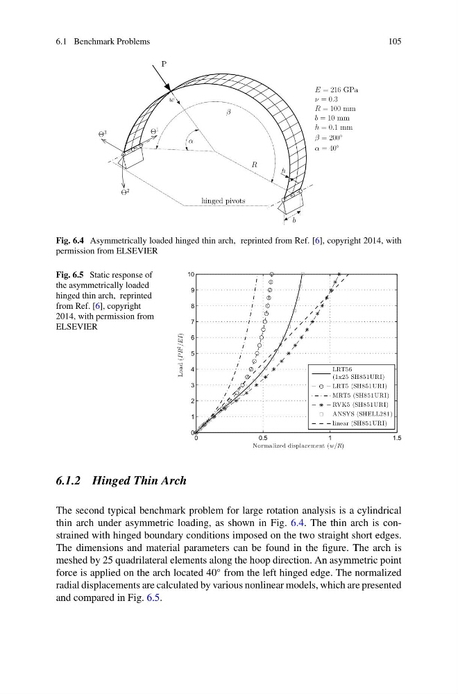
Fig. 6.4 Asymmetrically loaded hinged thin arch, reprinted from Ref. [6], copyright 2014, with
permission from ELSEVIER
Fig. 6.5 Static response of
the asymmetrically loaded
hinged thin arch, reprinted
from Ref. [6], copyright
2014, with permission from
ELSEVIER
0
0.5
1
1.5
0
1
2
3
4
5
6
7
8
9
10
Normalized displacement (w/R)
Load (P
R
2
/EI)
LRT56
(1x25 SH851URI)
LRT5 (SH851URI)
MRT5 (SH851URI)
RVK5 (SH851URI)
ANSYS (SHELL281)
linear (SH851URI)
6.1.2 Hinged Thin Arch
The second typical benchmark problem for large rotation analysis is a cylindrical
thin arch under asymmetric loading, as shown in Fig. 6.4. The thin arch is constrained with hinged boundary conditions imposed on the two straight short edges.
The dimensions and material parameters can be found in the figure. The arch is
meshed by 25 quadrilateral elements along the hoop direction. An asymmetric point
force is applied on the arch located 40
◦ from the left hinged edge. The normalized
radial displacements are calculated by various nonlinear models, which are presented
and compared in Fig. 6.5.
105
R
α
b
P
β
w
h
Θ
3
Θ
1
Θ
2
hinged pivots
R = 100 mm
b = 10 mm
h = 0.1 mm
β = 200
◦
α = 40
◦
ν = 0.3
E = 216 GPa
Fig. 6.4 Asymmetrically loaded hinged thin arch, reprinted from Ref. [6], copyright 2014, with
permission from ELSEVIER
Fig. 6.5 Static response of
the asymmetrically loaded
hinged thin arch, reprinted
from Ref. [6], copyright
2014, with permission from
ELSEVIER
0
0.5
1
1.5
0
1
2
3
4
5
6
7
8
9
10
Normalized displacement (w/R)
Load (P
R
2
/EI)
LRT56
(1x25 SH851URI)
LRT5 (SH851URI)
MRT5 (SH851URI)
RVK5 (SH851URI)
ANSYS (SHELL281)
linear (SH851URI)
6.1.2 Hinged Thin Arch
The second typical benchmark problem for large rotation analysis is a cylindrical
thin arch under asymmetric loading, as shown in Fig. 6.4. The thin arch is constrained with hinged boundary conditions imposed on the two straight short edges.
The dimensions and material parameters can be found in the figure. The arch is
meshed by 25 quadrilateral elements along the hoop direction. An asymmetric point
force is applied on the arch located 40
◦ from the left hinged edge. The normalized
radial displacements are calculated by various nonlinear models, which are presented
and compared in Fig. 6.5.