

5.2 Rotation Description
81
with
Rot = R X · R Y =
⎡
⎣
cos (ϕ 1 ) − sin (ϕ 1 ) sin (ϕ 2 ) sin (ϕ 1 ) cos (ϕ 2 )
0
cos (ϕ 2 )
sin (ϕ 2 )
− sin (ϕ 1 ) − cos (ϕ 1 ) sin (ϕ 2 ) cos (ϕ 1 ) cos (ϕ 2 )
⎤
⎦ , (5.13)
Rot
−1
=
⎡
⎣
cos (ϕ 1 )
0
− sin (ϕ 1 )
− sin (ϕ 1 ) sin (ϕ 2 ) cos (ϕ 2 ) − cos (ϕ 1 ) sin (ϕ 2 )
sin (ϕ 1 ) cos (ϕ 2 ) sin (ϕ 2 ) cos (ϕ 1 ) cos (ϕ 2 )
⎤
⎦ . (5.14)
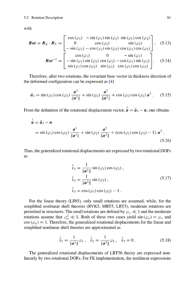
Therefore, after two rotations, the covariant base vector in thickness direction of
the deformed configuration can be expressed as [4]
¯
a 3 = sin (ϕ 1 ) cos (ϕ 2 )
a
1
a 1
+ sin (ϕ 2 )
a
2
a 2
+ cos (ϕ 1 ) cos (ϕ 2 ) a
3
.
(5.15)
From the definition of the rotational displacement vector,
1
u = ¯
a 3 − n, one obtains
1
u = ¯
a 3 − n
= sin (ϕ 1 ) cos (ϕ 2 )
a
1
a 1
+ sin (ϕ 2 )
a
2
a 2
+ (cos (ϕ 1 ) cos (ϕ 2 ) − 1) a
3
.
(5.16)
Thus, the generalized rotational displacements are expressed by two rotational DOFs
as
1
v 1 =
1
a 1
sin (ϕ 1 ) cos (ϕ 2 ) ,
1
v 2 =
1
a 2
sin (ϕ 2 ) ,
1
v 3 = cos (ϕ 1 ) cos (ϕ 2 ) − 1 .
(5.17)
For the linear theory (LIN5), only small rotations are assumed, while, for the
simplified nonlinear shell theories (RVK5, MRT5, LRT5), moderate rotations are
permitted in structures. The small rotations are defined by ϕ α 1 and the moderate
rotations assume that ϕ
2
α 1. Both of these two cases yield sin (ϕ α ) = ϕ α and
cos (ϕ α ) = 1. Therefore, the generalized rotational displacements for the linear and
simplified nonlinear shell theories are approximated as
1
v 1 =
1
a 1
ϕ 1 ,
1
v 2 =
1
a 2
ϕ 2 ,
1
v 3 = 0 .
(5.18)
The generalized rotational displacements of LRT56 theory are expressed nonlinearly by two rotational DOFs. For FE implementation, the nonlinear expressions
81
with
Rot = R X · R Y =
⎡
⎣
cos (ϕ 1 ) − sin (ϕ 1 ) sin (ϕ 2 ) sin (ϕ 1 ) cos (ϕ 2 )
0
cos (ϕ 2 )
sin (ϕ 2 )
− sin (ϕ 1 ) − cos (ϕ 1 ) sin (ϕ 2 ) cos (ϕ 1 ) cos (ϕ 2 )
⎤
⎦ , (5.13)
Rot
−1
=
⎡
⎣
cos (ϕ 1 )
0
− sin (ϕ 1 )
− sin (ϕ 1 ) sin (ϕ 2 ) cos (ϕ 2 ) − cos (ϕ 1 ) sin (ϕ 2 )
sin (ϕ 1 ) cos (ϕ 2 ) sin (ϕ 2 ) cos (ϕ 1 ) cos (ϕ 2 )
⎤
⎦ . (5.14)
Therefore, after two rotations, the covariant base vector in thickness direction of
the deformed configuration can be expressed as [4]
¯
a 3 = sin (ϕ 1 ) cos (ϕ 2 )
a
1
a 1
+ sin (ϕ 2 )
a
2
a 2
+ cos (ϕ 1 ) cos (ϕ 2 ) a
3
.
(5.15)
From the definition of the rotational displacement vector,
1
u = ¯
a 3 − n, one obtains
1
u = ¯
a 3 − n
= sin (ϕ 1 ) cos (ϕ 2 )
a
1
a 1
+ sin (ϕ 2 )
a
2
a 2
+ (cos (ϕ 1 ) cos (ϕ 2 ) − 1) a
3
.
(5.16)
Thus, the generalized rotational displacements are expressed by two rotational DOFs
as
1
v 1 =
1
a 1
sin (ϕ 1 ) cos (ϕ 2 ) ,
1
v 2 =
1
a 2
sin (ϕ 2 ) ,
1
v 3 = cos (ϕ 1 ) cos (ϕ 2 ) − 1 .
(5.17)
For the linear theory (LIN5), only small rotations are assumed, while, for the
simplified nonlinear shell theories (RVK5, MRT5, LRT5), moderate rotations are
permitted in structures. The small rotations are defined by ϕ α 1 and the moderate
rotations assume that ϕ
2
α 1. Both of these two cases yield sin (ϕ α ) = ϕ α and
cos (ϕ α ) = 1. Therefore, the generalized rotational displacements for the linear and
simplified nonlinear shell theories are approximated as
1
v 1 =
1
a 1
ϕ 1 ,
1
v 2 =
1
a 2
ϕ 2 ,
1
v 3 = 0 .
(5.18)
The generalized rotational displacements of LRT56 theory are expressed nonlinearly by two rotational DOFs. For FE implementation, the nonlinear expressions