

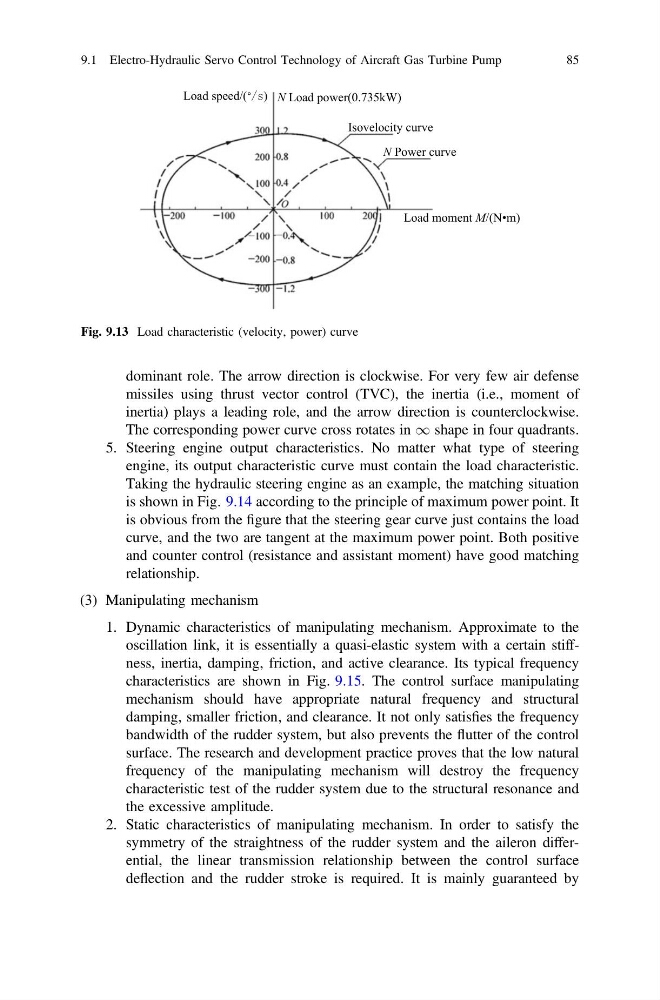
dominant role. The arrow direction is clockwise. For very few air defense
missiles using thrust vector control (TVC), the inertia (i.e., moment of
inertia) plays a leading role, and the arrow direction is counterclockwise.
The corresponding power curve cross rotates in 1 shape in four quadrants.
5. Steering engine output characteristics. No matter what type of steering
engine, its output characteristic curve must contain the load characteristic.
Taking the hydraulic steering engine as an example, the matching situation
is shown in Fig. 9.14 according to the principle of maximum power point. It
is obvious from the figure that the steering gear curve just contains the load
curve, and the two are tangent at the maximum power point. Both positive
and counter control (resistance and assistant moment) have good matching
relationship.
(3) Manipulating mechanism
1. Dynamic characteristics of manipulating mechanism. Approximate to the
oscillation link, it is essentially a quasi-elastic system with a certain stiffness, inertia, damping, friction, and active clearance. Its typical frequency
characteristics are shown in Fig. 9.15. The control surface manipulating
mechanism should have appropriate natural frequency and structural
damping, smaller friction, and clearance. It not only satisfies the frequency
bandwidth of the rudder system, but also prevents the flutter of the control
surface. The research and development practice proves that the low natural
frequency of the manipulating mechanism will destroy the frequency
characteristic test of the rudder system due to the structural resonance and
the excessive amplitude.
2. Static characteristics of manipulating mechanism. In order to satisfy the
symmetry of the straightness of the rudder system and the aileron differential, the linear transmission relationship between the control surface
deflection and the rudder stroke is required. It is mainly guaranteed by
Load speed/(° ) N Load power(0.735kW)
Isovelocity curve
N Power curve
Load moment M/(N•m)
Fig. 9.13 Load characteristic (velocity, power) curve
9.1 Electro-Hydraulic Servo Control Technology of Aircraft Gas Turbine Pump
85
missiles using thrust vector control (TVC), the inertia (i.e., moment of
inertia) plays a leading role, and the arrow direction is counterclockwise.
The corresponding power curve cross rotates in 1 shape in four quadrants.
5. Steering engine output characteristics. No matter what type of steering
engine, its output characteristic curve must contain the load characteristic.
Taking the hydraulic steering engine as an example, the matching situation
is shown in Fig. 9.14 according to the principle of maximum power point. It
is obvious from the figure that the steering gear curve just contains the load
curve, and the two are tangent at the maximum power point. Both positive
and counter control (resistance and assistant moment) have good matching
relationship.
(3) Manipulating mechanism
1. Dynamic characteristics of manipulating mechanism. Approximate to the
oscillation link, it is essentially a quasi-elastic system with a certain stiffness, inertia, damping, friction, and active clearance. Its typical frequency
characteristics are shown in Fig. 9.15. The control surface manipulating
mechanism should have appropriate natural frequency and structural
damping, smaller friction, and clearance. It not only satisfies the frequency
bandwidth of the rudder system, but also prevents the flutter of the control
surface. The research and development practice proves that the low natural
frequency of the manipulating mechanism will destroy the frequency
characteristic test of the rudder system due to the structural resonance and
the excessive amplitude.
2. Static characteristics of manipulating mechanism. In order to satisfy the
symmetry of the straightness of the rudder system and the aileron differential, the linear transmission relationship between the control surface
deflection and the rudder stroke is required. It is mainly guaranteed by
Load speed/(° ) N Load power(0.735kW)
Isovelocity curve
N Power curve
Load moment M/(N•m)
Fig. 9.13 Load characteristic (velocity, power) curve
9.1 Electro-Hydraulic Servo Control Technology of Aircraft Gas Turbine Pump
85