

the actuators have no redundancy. Reasonable layout is needed to reduce
weight and volume.
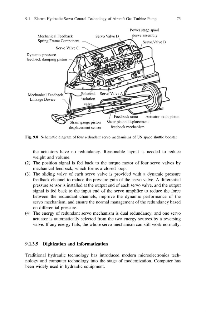
(2) The position signal is fed back to the torque motor of four servo valves by
mechanical feedback, which forms a closed loop.
(3) The sliding valve of each servo valve is provided with a dynamic pressure
feedback channel to reduce the pressure gain of the servo valve. A differential
pressure sensor is installed at the output end of each servo valve, and the output
signal is fed back to the input end of the servo amplifier to reduce the force
between the redundant channels, improve the dynamic performance of the
servo mechanism, and ensure the normal management of the redundancy based
on differential pressure.
(4) The energy of redundant servo mechanism is dual redundancy, and one servo
actuator is automatically selected from the two energy sources by a reversing
valve. If any energy fails, the whole servo mechanism can still work normally.
9.1.3.5 Digitization and Informatization
Traditional hydraulic technology has introduced modern microelectronics technology and computer technology into the stage of modernization. Computer has
been widely used in hydraulic equipment.
Mechanical Feedback
Spring Frame Component
Servo Valve C
Dynamic pressure
feedback damping piston
Mechanical Feedback
Linkage Device
Strain gauge piston
displacement sensor
Feedback cone
Shear piston displacement
feedback mechanism
Actuator main piston
Servo Valve D
Power stage spool
sleeve assembly
Servo Valve B
Servo Valve A
Solenoid
isolation
valve
Fig. 9.8 Schematic diagram of four redundant servo mechanisms of US space shuttle booster
9.1 Electro-Hydraulic Servo Control Technology of Aircraft Gas Turbine Pump
73
weight and volume.
(2) The position signal is fed back to the torque motor of four servo valves by
mechanical feedback, which forms a closed loop.
(3) The sliding valve of each servo valve is provided with a dynamic pressure
feedback channel to reduce the pressure gain of the servo valve. A differential
pressure sensor is installed at the output end of each servo valve, and the output
signal is fed back to the input end of the servo amplifier to reduce the force
between the redundant channels, improve the dynamic performance of the
servo mechanism, and ensure the normal management of the redundancy based
on differential pressure.
(4) The energy of redundant servo mechanism is dual redundancy, and one servo
actuator is automatically selected from the two energy sources by a reversing
valve. If any energy fails, the whole servo mechanism can still work normally.
9.1.3.5 Digitization and Informatization
Traditional hydraulic technology has introduced modern microelectronics technology and computer technology into the stage of modernization. Computer has
been widely used in hydraulic equipment.
Mechanical Feedback
Spring Frame Component
Servo Valve C
Dynamic pressure
feedback damping piston
Mechanical Feedback
Linkage Device
Strain gauge piston
displacement sensor
Feedback cone
Shear piston displacement
feedback mechanism
Actuator main piston
Servo Valve D
Power stage spool
sleeve assembly
Servo Valve B
Servo Valve A
Solenoid
isolation
valve
Fig. 9.8 Schematic diagram of four redundant servo mechanisms of US space shuttle booster
9.1 Electro-Hydraulic Servo Control Technology of Aircraft Gas Turbine Pump
73