

transmissionation and hydrogenation characteristics are obtained by comparing the
theoretical results with the experimental results.
This section establishes the mathematical model of the relationship between
working time and pressure in the process of hydrogen transmissionation and
hydrogenation of high-pressure cylinders, and obtains the parameters relationship
of hydrogen storage mass of cylinders, working time of hydrogenation and driving
distance of vehicles in the hydrogen transmission system of clean energy vehicles.
13.2.1 Characteristics of Vehicle-Borne Hydrogen
Transmission and Storage System
13.2.1.1 Hydrogen Storage Mode
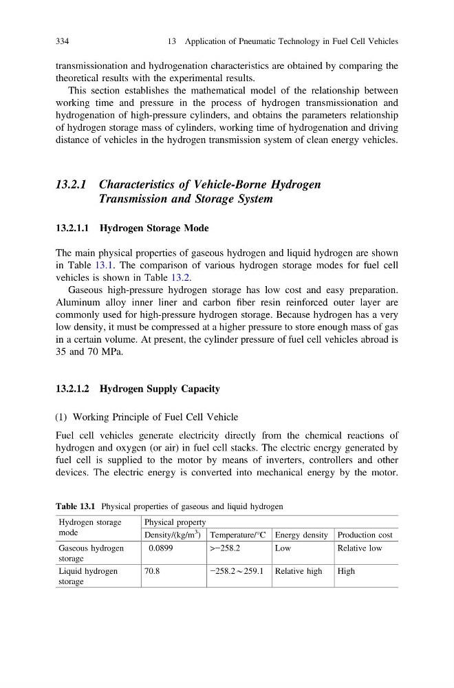
The main physical properties of gaseous hydrogen and liquid hydrogen are shown
in Table 13.1. The comparison of various hydrogen storage modes for fuel cell
vehicles is shown in Table 13.2.
Gaseous high-pressure hydrogen storage has low cost and easy preparation.
Aluminum alloy inner liner and carbon fiber resin reinforced outer layer are
commonly used for high-pressure hydrogen storage. Because hydrogen has a very
low density, it must be compressed at a higher pressure to store enough mass of gas
in a certain volume. At present, the cylinder pressure of fuel cell vehicles abroad is
35 and 70 MPa.
13.2.1.2 Hydrogen Supply Capacity
(1) Working Principle of Fuel Cell Vehicle
Fuel cell vehicles generate electricity directly from the chemical reactions of
hydrogen and oxygen (or air) in fuel cell stacks. The electric energy generated by
fuel cell is supplied to the motor by means of inverters, controllers and other
devices. The electric energy is converted into mechanical energy by the motor.
Table 13.1 Physical properties of gaseous and liquid hydrogen
Hydrogen storage
mode
Physical property
Density/(kg/m
3
) Temperature/°C Energy density Production cost
Gaseous hydrogen
storage
0.0899
>−258.2
Low
Relative low
Liquid hydrogen
storage
70.8
−258.2*259.1 Relative high
High
334
13 Application of Pneumatic Technology in Fuel Cell Vehicles
theoretical results with the experimental results.
This section establishes the mathematical model of the relationship between
working time and pressure in the process of hydrogen transmissionation and
hydrogenation of high-pressure cylinders, and obtains the parameters relationship
of hydrogen storage mass of cylinders, working time of hydrogenation and driving
distance of vehicles in the hydrogen transmission system of clean energy vehicles.
13.2.1 Characteristics of Vehicle-Borne Hydrogen
Transmission and Storage System
13.2.1.1 Hydrogen Storage Mode
The main physical properties of gaseous hydrogen and liquid hydrogen are shown
in Table 13.1. The comparison of various hydrogen storage modes for fuel cell
vehicles is shown in Table 13.2.
Gaseous high-pressure hydrogen storage has low cost and easy preparation.
Aluminum alloy inner liner and carbon fiber resin reinforced outer layer are
commonly used for high-pressure hydrogen storage. Because hydrogen has a very
low density, it must be compressed at a higher pressure to store enough mass of gas
in a certain volume. At present, the cylinder pressure of fuel cell vehicles abroad is
35 and 70 MPa.
13.2.1.2 Hydrogen Supply Capacity
(1) Working Principle of Fuel Cell Vehicle
Fuel cell vehicles generate electricity directly from the chemical reactions of
hydrogen and oxygen (or air) in fuel cell stacks. The electric energy generated by
fuel cell is supplied to the motor by means of inverters, controllers and other
devices. The electric energy is converted into mechanical energy by the motor.
Table 13.1 Physical properties of gaseous and liquid hydrogen
Hydrogen storage
mode
Physical property
Density/(kg/m
3
) Temperature/°C Energy density Production cost
Gaseous hydrogen
storage
0.0899
>−258.2
Low
Relative low
Liquid hydrogen
storage
70.8
−258.2*259.1 Relative high
High
334
13 Application of Pneumatic Technology in Fuel Cell Vehicles