

d st Static displacement produced by gravity acting on an elastic rod in the form of
static load;
G Hammer weight.
Taking a cylindrical steel pipe pile manufactured by a company as an example,
the material is Q345C, the elastic modulus E is 206 GPa and the shear modulus G is
79 GPa, Poisson’s ratio l is 0.3, diameter D ¼ 1200 mm, wall thickness
d ¼ 150 mm, total length l is 10 m, in which the length of soil infiltration is
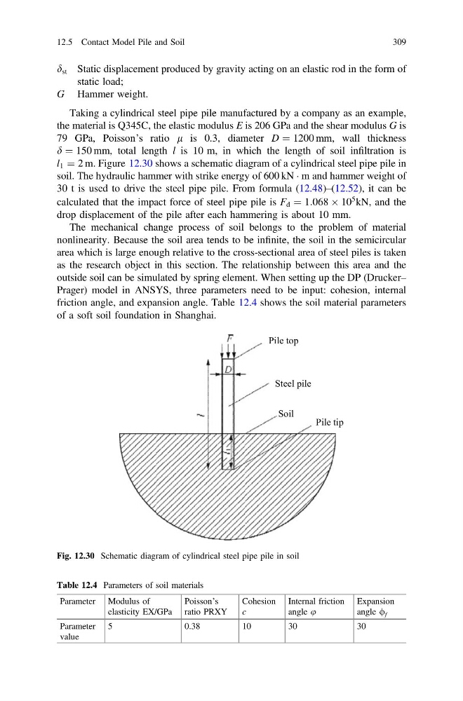
l 1 ¼ 2 m. Figure 12.30 shows a schematic diagram of a cylindrical steel pipe pile in
soil. The hydraulic hammer with strike energy of 600 kN Á m and hammer weight of
30 t is used to drive the steel pipe pile. From formula (12.48)–(12.52), it can be
calculated that the impact force of steel pipe pile is F d ¼ 1:068 Â 10
5 kN, and the
drop displacement of the pile after each hammering is about 10 mm.
The mechanical change process of soil belongs to the problem of material
nonlinearity. Because the soil area tends to be infinite, the soil in the semicircular
area which is large enough relative to the cross-sectional area of steel piles is taken
as the research object in this section. The relationship between this area and the
outside soil can be simulated by spring element. When setting up the DP (Drucker–
Prager) model in ANSYS, three parameters need to be input: cohesion, internal
friction angle, and expansion angle. Table 12.4 shows the soil material parameters
of a soft soil foundation in Shanghai.
Pile top
Steel pile
Soil
Pile tip
Fig. 12.30 Schematic diagram of cylindrical steel pipe pile in soil
Table 12.4 Parameters of soil materials
Parameter Modulus of
elasticity EX/GPa
Poisson’s
ratio PRXY
Cohesion
c
Internal friction
angle u
Expansion
angle / f
Parameter
value
5
0.38
10
30
30
12.5 Contact Model Pile and Soil
309
static load;
G Hammer weight.
Taking a cylindrical steel pipe pile manufactured by a company as an example,
the material is Q345C, the elastic modulus E is 206 GPa and the shear modulus G is
79 GPa, Poisson’s ratio l is 0.3, diameter D ¼ 1200 mm, wall thickness
d ¼ 150 mm, total length l is 10 m, in which the length of soil infiltration is
l 1 ¼ 2 m. Figure 12.30 shows a schematic diagram of a cylindrical steel pipe pile in
soil. The hydraulic hammer with strike energy of 600 kN Á m and hammer weight of
30 t is used to drive the steel pipe pile. From formula (12.48)–(12.52), it can be
calculated that the impact force of steel pipe pile is F d ¼ 1:068 Â 10
5 kN, and the
drop displacement of the pile after each hammering is about 10 mm.
The mechanical change process of soil belongs to the problem of material
nonlinearity. Because the soil area tends to be infinite, the soil in the semicircular
area which is large enough relative to the cross-sectional area of steel piles is taken
as the research object in this section. The relationship between this area and the
outside soil can be simulated by spring element. When setting up the DP (Drucker–
Prager) model in ANSYS, three parameters need to be input: cohesion, internal
friction angle, and expansion angle. Table 12.4 shows the soil material parameters
of a soft soil foundation in Shanghai.
Pile top
Steel pile
Soil
Pile tip
Fig. 12.30 Schematic diagram of cylindrical steel pipe pile in soil
Table 12.4 Parameters of soil materials
Parameter Modulus of
elasticity EX/GPa
Poisson’s
ratio PRXY
Cohesion
c
Internal friction
angle u
Expansion
angle / f
Parameter
value
5
0.38
10
30
30
12.5 Contact Model Pile and Soil
309