

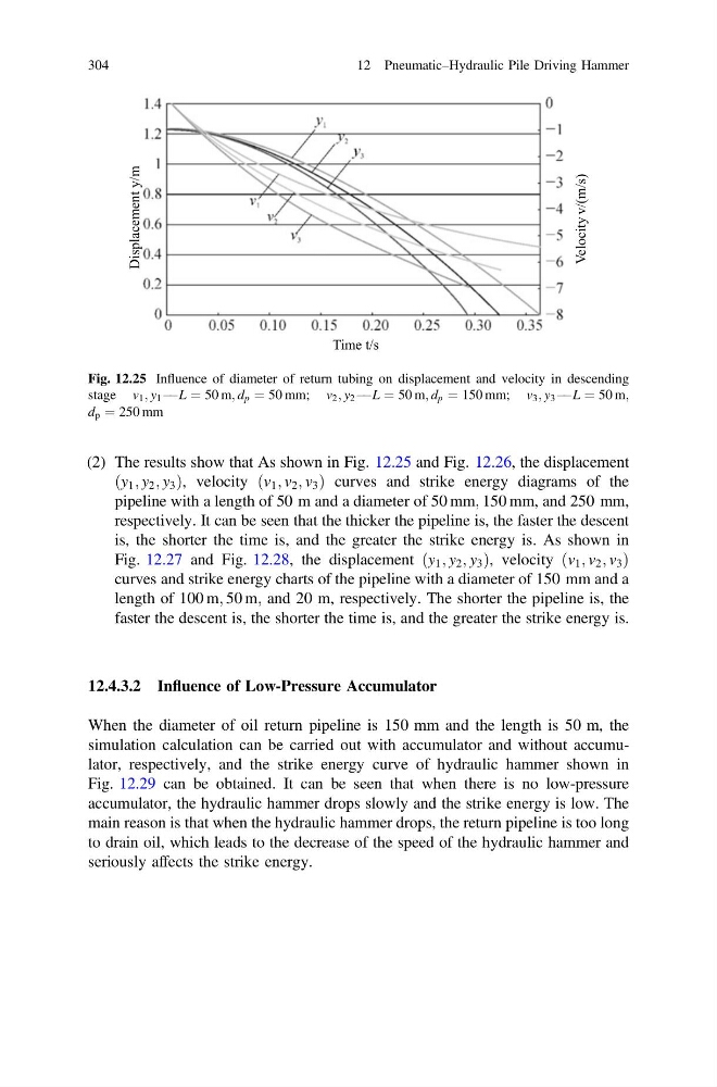
(2) The results show that As shown in Fig. 12.25 and Fig. 12.26, the displacement
ðy 1 ; y 2 ; y 3 Þ, velocity ðv 1 ; v 2 ; v 3 Þ curves and strike energy diagrams of the
pipeline with a length of 50 m and a diameter of 50 mm; 150 mm, and 250 mm,
respectively. It can be seen that the thicker the pipeline is, the faster the descent
is, the shorter the time is, and the greater the strike energy is. As shown in
Fig. 12.27 and Fig. 12.28, the displacement ðy 1 ; y 2 ; y 3 Þ, velocity ðv 1 ; v 2 ; v 3 Þ
curves and strike energy charts of the pipeline with a diameter of 150 mm and a
length of 100 m; 50 m; and 20 m, respectively. The shorter the pipeline is, the
faster the descent is, the shorter the time is, and the greater the strike energy is.
12.4.3.2 Influence of Low-Pressure Accumulator
When the diameter of oil return pipeline is 150 mm and the length is 50 m, the
simulation calculation can be carried out with accumulator and without accumulator, respectively, and the strike energy curve of hydraulic hammer shown in
Fig. 12.29 can be obtained. It can be seen that when there is no low-pressure
accumulator, the hydraulic hammer drops slowly and the strike energy is low. The
main reason is that when the hydraulic hammer drops, the return pipeline is too long
to drain oil, which leads to the decrease of the speed of the hydraulic hammer and
seriously affects the strike energy.
Time t/s
Velocity v/(m/s)
Displacement y/m
Fig. 12.25 Influence of diameter of return tubing on displacement and velocity in descending
stage v 1 ; y 1 À ÀL ¼ 50 m; d p ¼ 50 mm; v 2 ; y 2 À ÀL ¼ 50 m; d p ¼ 150 mm; v 3 ; y 3 À ÀL ¼ 50 m;
d p ¼ 250 mm
304
12 Pneumatic–Hydraulic Pile Driving Hammer
ðy 1 ; y 2 ; y 3 Þ, velocity ðv 1 ; v 2 ; v 3 Þ curves and strike energy diagrams of the
pipeline with a length of 50 m and a diameter of 50 mm; 150 mm, and 250 mm,
respectively. It can be seen that the thicker the pipeline is, the faster the descent
is, the shorter the time is, and the greater the strike energy is. As shown in
Fig. 12.27 and Fig. 12.28, the displacement ðy 1 ; y 2 ; y 3 Þ, velocity ðv 1 ; v 2 ; v 3 Þ
curves and strike energy charts of the pipeline with a diameter of 150 mm and a
length of 100 m; 50 m; and 20 m, respectively. The shorter the pipeline is, the
faster the descent is, the shorter the time is, and the greater the strike energy is.
12.4.3.2 Influence of Low-Pressure Accumulator
When the diameter of oil return pipeline is 150 mm and the length is 50 m, the
simulation calculation can be carried out with accumulator and without accumulator, respectively, and the strike energy curve of hydraulic hammer shown in
Fig. 12.29 can be obtained. It can be seen that when there is no low-pressure
accumulator, the hydraulic hammer drops slowly and the strike energy is low. The
main reason is that when the hydraulic hammer drops, the return pipeline is too long
to drain oil, which leads to the decrease of the speed of the hydraulic hammer and
seriously affects the strike energy.
Time t/s
Velocity v/(m/s)
Displacement y/m
Fig. 12.25 Influence of diameter of return tubing on displacement and velocity in descending
stage v 1 ; y 1 À ÀL ¼ 50 m; d p ¼ 50 mm; v 2 ; y 2 À ÀL ¼ 50 m; d p ¼ 150 mm; v 3 ; y 3 À ÀL ¼ 50 m;
d p ¼ 250 mm
304
12 Pneumatic–Hydraulic Pile Driving Hammer