

low-pressure accumulator 3 absorbs part of the hydraulic oil from the lower
chamber of the hydraulic cylinder to accelerate the downward movement of the
hammer. When the two solenoid reversing valves are in the closed position, the
hydraulic oil enters the hydraulic cylinder from the hydraulic pump 8 through
the electromagnetic reversing valve 6, and unloads the hydraulic system through the
electromagnetic reversing valve 4 return tank and the low-pressure accumulator 3
and the hydraulic oil return tank.
The hydraulic–pneumatic acceleration hammer is equipped with a nitrogen
chamber in the upper structure of the hydraulic cylinder. The gas pressure can be set
independently of the hydraulic system to change the falling acceleration of the
hammer and realize stepless control of the hammer energy. Utilizing the compressibility of nitrogen gas, energy is absorbed and stored in the process of hammer
rising. The hammer head and piston can adopt the whole forged alloy steel structure
and be installed in the fully enclosed cylinder body. The structure of the hammer
head and piston is simple and compact. The strike energy of the hydraulic hammer
is mainly related to the weight of the hammer, the lifting height of the hammer and
the acceleration of the hammer. When the hydraulic hammer drops, the acceleration
of the hammer body can reach more than 2.0 g through the dual action of
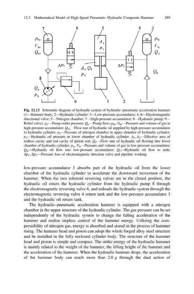
Fig. 12.12 Schematic diagram of hydraulic system of hydraulic–pneumatic acceleration hammer
(1—Hammer body; 2—Hydraulic cylinder; 3—Low-pressure accumulator; 4, 6—Electromagnetic
directional valve; 5—Nitrogen chamber; 7—High-pressure accumulator; 8—Hydraulic pump; 9—
Relief valve). p p —Pump outlet pressure; Q p —Pump flow; p ha ; V ha —Pressure and volume of gas in
high-pressure accumulator; Q ha —Flow rate of hydraulic oil supplied by high-pressure accumulator
to hydraulic cylinder; p u —Pressure of nitrogen chamber in upper chamber of hydraulic cylinder;
p d —Hydraulic oil pressure in lower chamber of hydraulic cylinder; A u ; A d —Effective area of
rodless cavity and rod cavity of piston rod; Q d —Flow rate of hydraulic oil flowing into lower
chamber of hydraulic cylinder; p la ; V la —Pressure and volume of gas in low-pressure accumulator;
Q la —Hydraulic oil flow into low-pressure accumulator; Q h —Hydraulic oil flow to tank;
Dp 1 ; Dp 2 —Pressure loss of electromagnetic direction valve and pipeline working
12.3 Mathematical Model of High-Speed Pneumatic–Hydraulic Composite Hammer
289
chamber of the hydraulic cylinder to accelerate the downward movement of the
hammer. When the two solenoid reversing valves are in the closed position, the
hydraulic oil enters the hydraulic cylinder from the hydraulic pump 8 through
the electromagnetic reversing valve 6, and unloads the hydraulic system through the
electromagnetic reversing valve 4 return tank and the low-pressure accumulator 3
and the hydraulic oil return tank.
The hydraulic–pneumatic acceleration hammer is equipped with a nitrogen
chamber in the upper structure of the hydraulic cylinder. The gas pressure can be set
independently of the hydraulic system to change the falling acceleration of the
hammer and realize stepless control of the hammer energy. Utilizing the compressibility of nitrogen gas, energy is absorbed and stored in the process of hammer
rising. The hammer head and piston can adopt the whole forged alloy steel structure
and be installed in the fully enclosed cylinder body. The structure of the hammer
head and piston is simple and compact. The strike energy of the hydraulic hammer
is mainly related to the weight of the hammer, the lifting height of the hammer and
the acceleration of the hammer. When the hydraulic hammer drops, the acceleration
of the hammer body can reach more than 2.0 g through the dual action of
Fig. 12.12 Schematic diagram of hydraulic system of hydraulic–pneumatic acceleration hammer
(1—Hammer body; 2—Hydraulic cylinder; 3—Low-pressure accumulator; 4, 6—Electromagnetic
directional valve; 5—Nitrogen chamber; 7—High-pressure accumulator; 8—Hydraulic pump; 9—
Relief valve). p p —Pump outlet pressure; Q p —Pump flow; p ha ; V ha —Pressure and volume of gas in
high-pressure accumulator; Q ha —Flow rate of hydraulic oil supplied by high-pressure accumulator
to hydraulic cylinder; p u —Pressure of nitrogen chamber in upper chamber of hydraulic cylinder;
p d —Hydraulic oil pressure in lower chamber of hydraulic cylinder; A u ; A d —Effective area of
rodless cavity and rod cavity of piston rod; Q d —Flow rate of hydraulic oil flowing into lower
chamber of hydraulic cylinder; p la ; V la —Pressure and volume of gas in low-pressure accumulator;
Q la —Hydraulic oil flow into low-pressure accumulator; Q h —Hydraulic oil flow to tank;
Dp 1 ; Dp 2 —Pressure loss of electromagnetic direction valve and pipeline working
12.3 Mathematical Model of High-Speed Pneumatic–Hydraulic Composite Hammer
289