

12.2.1 Hydraulic System of Pneumatic–Hydraulic Pile
Driving Hammer
12.2.1.1 Principle of Pneumatic–Hydraulic Pile Driving Hammer
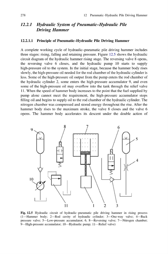
A complete working cycle of hydraulic–pneumatic pile driving hammer includes
three stages: rising, falling and retaining pressure. Figure 12.5 shows the hydraulic
circuit diagram of the hydraulic hammer rising stage. The reversing valve 8 opens,
the reversing valve 6 closes, and the hydraulic pump 10 starts to supply
high-pressure oil to the system. In the initial stage, because the hammer body rises
slowly, the high-pressure oil needed for the rod chamber of the hydraulic cylinder is
less. Some of the high-pressure oil output from the pump enters the rod chamber of
the hydraulic cylinder 2, some enters the high-pressure accumulator 9, and even
some of the high-pressure oil may overflow into the tank through the relief valve
11. When the speed of hammer body increases to the point that the fuel supplied by
pump alone cannot meet the requirement, the high-pressure accumulator stops
filling oil and begins to supply oil to the rod chamber of the hydraulic cylinder. The
nitrogen chamber was compressed and stored energy throughout the rise. After the
hammer body rises to the maximum stroke, the valve 8 closes and the valve 6
opens. The hammer body accelerates its descent under the double action of
Fig. 12.5 Hydraulic circuit of hydraulic–pneumatic pile driving hammer in rising process
(1—Hammer body; 2—Rod cavity of hydraulic cylinder; 3—One-way valve; 4—Back
pressure valve; 5—Low-pressure accumulator; 6, 8—Reversing valve; 7—Nitrogen chamber;
9—High-pressure accumulator; 10—Hydraulic pump; 11—Relief valve)
278
12 Pneumatic–Hydraulic Pile Driving Hammer
Driving Hammer
12.2.1.1 Principle of Pneumatic–Hydraulic Pile Driving Hammer
A complete working cycle of hydraulic–pneumatic pile driving hammer includes
three stages: rising, falling and retaining pressure. Figure 12.5 shows the hydraulic
circuit diagram of the hydraulic hammer rising stage. The reversing valve 8 opens,
the reversing valve 6 closes, and the hydraulic pump 10 starts to supply
high-pressure oil to the system. In the initial stage, because the hammer body rises
slowly, the high-pressure oil needed for the rod chamber of the hydraulic cylinder is
less. Some of the high-pressure oil output from the pump enters the rod chamber of
the hydraulic cylinder 2, some enters the high-pressure accumulator 9, and even
some of the high-pressure oil may overflow into the tank through the relief valve
11. When the speed of hammer body increases to the point that the fuel supplied by
pump alone cannot meet the requirement, the high-pressure accumulator stops
filling oil and begins to supply oil to the rod chamber of the hydraulic cylinder. The
nitrogen chamber was compressed and stored energy throughout the rise. After the
hammer body rises to the maximum stroke, the valve 8 closes and the valve 6
opens. The hammer body accelerates its descent under the double action of
Fig. 12.5 Hydraulic circuit of hydraulic–pneumatic pile driving hammer in rising process
(1—Hammer body; 2—Rod cavity of hydraulic cylinder; 3—One-way valve; 4—Back
pressure valve; 5—Low-pressure accumulator; 6, 8—Reversing valve; 7—Nitrogen chamber;
9—High-pressure accumulator; 10—Hydraulic pump; 11—Relief valve)
278
12 Pneumatic–Hydraulic Pile Driving Hammer