

start a new cycle. When the pile hammer stops working, the relief valve 2 and the
unloading valve 4 are opened and connected with the oil tank. The pressure oil from
the variable pump 1 flows directly back to the oil tank. The upper and lower
chambers of the hydraulic cylinder 8 are connected with the same pressure. The
piston stops at the lowest end of the hydraulic cylinder 8.
12.1.1.3 Dutch IHC Double Acting Hydraulic Hammer
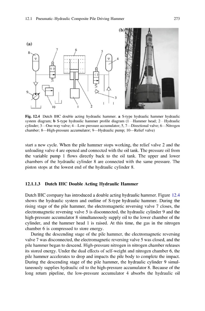
Dutch IHC company has introduced a double acting hydraulic hammer. Figure 12.4
shows the hydraulic system and outline of S-type hydraulic hammer. During the
rising stage of the pile hammer, the electromagnetic reversing valve 7 closes, the
electromagnetic reversing valve 5 is disconnected, the hydraulic cylinder 9 and the
high-pressure accumulator 8 simultaneously supply oil to the lower chamber of the
cylinder, and the hammer head 1 is raised. At this time, the gas in the nitrogen
chamber 6 is compressed to store energy.
During the descending stage of the pile hammer, the electromagnetic reversing
valve 7 was disconnected, the electromagnetic reversing valve 5 was closed, and the
pile hammer began to descend. High-pressure nitrogen in nitrogen chamber releases
its stored energy. Under the dual effects of self-weight and nitrogen chamber 6, the
pile hammer accelerates to drop and impacts the pile body to complete the impact.
During the descending stage of the pile hammer, the hydraulic cylinder 9 simultaneously supplies hydraulic oil to the high-pressure accumulator 8. Because of the
long return pipeline, the low-pressure accumulator 4 absorbs the hydraulic oil
Fig. 12.4 Dutch IHC double acting hydraulic hammer. a S-type hydraulic hammer hydraulic
system diagram; b S-type hydraulic hammer profile diagram (1—Hammer head; 2—Hydraulic
cylinder; 3—One-way valve; 4—Low-pressure accumulator; 5, 7—Directional valve; 6—Nitrogen
chamber; 8—High-pressure accumulator; 9—Hydraulic pump; 10—Relief valve)
12.1 Pneumatic–Hydraulic Composite Pile Driving Hammer
273
unloading valve 4 are opened and connected with the oil tank. The pressure oil from
the variable pump 1 flows directly back to the oil tank. The upper and lower
chambers of the hydraulic cylinder 8 are connected with the same pressure. The
piston stops at the lowest end of the hydraulic cylinder 8.
12.1.1.3 Dutch IHC Double Acting Hydraulic Hammer
Dutch IHC company has introduced a double acting hydraulic hammer. Figure 12.4
shows the hydraulic system and outline of S-type hydraulic hammer. During the
rising stage of the pile hammer, the electromagnetic reversing valve 7 closes, the
electromagnetic reversing valve 5 is disconnected, the hydraulic cylinder 9 and the
high-pressure accumulator 8 simultaneously supply oil to the lower chamber of the
cylinder, and the hammer head 1 is raised. At this time, the gas in the nitrogen
chamber 6 is compressed to store energy.
During the descending stage of the pile hammer, the electromagnetic reversing
valve 7 was disconnected, the electromagnetic reversing valve 5 was closed, and the
pile hammer began to descend. High-pressure nitrogen in nitrogen chamber releases
its stored energy. Under the dual effects of self-weight and nitrogen chamber 6, the
pile hammer accelerates to drop and impacts the pile body to complete the impact.
During the descending stage of the pile hammer, the hydraulic cylinder 9 simultaneously supplies hydraulic oil to the high-pressure accumulator 8. Because of the
long return pipeline, the low-pressure accumulator 4 absorbs the hydraulic oil
Fig. 12.4 Dutch IHC double acting hydraulic hammer. a S-type hydraulic hammer hydraulic
system diagram; b S-type hydraulic hammer profile diagram (1—Hammer head; 2—Hydraulic
cylinder; 3—One-way valve; 4—Low-pressure accumulator; 5, 7—Directional valve; 6—Nitrogen
chamber; 8—High-pressure accumulator; 9—Hydraulic pump; 10—Relief valve)
12.1 Pneumatic–Hydraulic Composite Pile Driving Hammer
273