

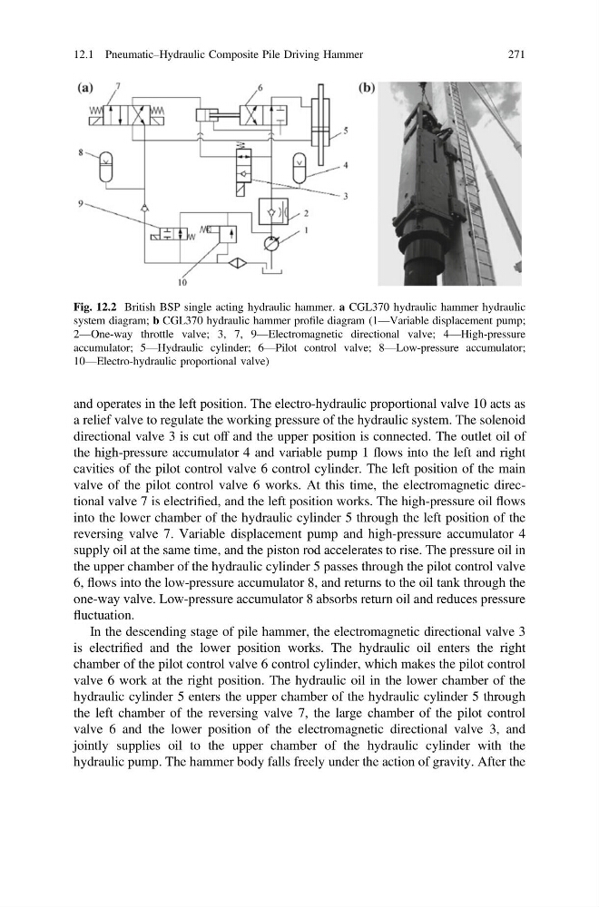
and operates in the left position. The electro-hydraulic proportional valve 10 acts as
a relief valve to regulate the working pressure of the hydraulic system. The solenoid
directional valve 3 is cut off and the upper position is connected. The outlet oil of
the high-pressure accumulator 4 and variable pump 1 flows into the left and right
cavities of the pilot control valve 6 control cylinder. The left position of the main
valve of the pilot control valve 6 works. At this time, the electromagnetic directional valve 7 is electrified, and the left position works. The high-pressure oil flows
into the lower chamber of the hydraulic cylinder 5 through the left position of the
reversing valve 7. Variable displacement pump and high-pressure accumulator 4
supply oil at the same time, and the piston rod accelerates to rise. The pressure oil in
the upper chamber of the hydraulic cylinder 5 passes through the pilot control valve
6, flows into the low-pressure accumulator 8, and returns to the oil tank through the
one-way valve. Low-pressure accumulator 8 absorbs return oil and reduces pressure
fluctuation.
In the descending stage of pile hammer, the electromagnetic directional valve 3
is electrified and the lower position works. The hydraulic oil enters the right
chamber of the pilot control valve 6 control cylinder, which makes the pilot control
valve 6 work at the right position. The hydraulic oil in the lower chamber of the
hydraulic cylinder 5 enters the upper chamber of the hydraulic cylinder 5 through
the left chamber of the reversing valve 7, the large chamber of the pilot control
valve 6 and the lower position of the electromagnetic directional valve 3, and
jointly supplies oil to the upper chamber of the hydraulic cylinder with the
hydraulic pump. The hammer body falls freely under the action of gravity. After the
Fig. 12.2 British BSP single acting hydraulic hammer. a CGL370 hydraulic hammer hydraulic
system diagram; b CGL370 hydraulic hammer profile diagram (1—Variable displacement pump;
2—One-way throttle valve; 3, 7, 9—Electromagnetic directional valve; 4—High-pressure
accumulator; 5—Hydraulic cylinder; 6—Pilot control valve; 8—Low-pressure accumulator;
10—Electro-hydraulic proportional valve)
12.1 Pneumatic–Hydraulic Composite Pile Driving Hammer
271
a relief valve to regulate the working pressure of the hydraulic system. The solenoid
directional valve 3 is cut off and the upper position is connected. The outlet oil of
the high-pressure accumulator 4 and variable pump 1 flows into the left and right
cavities of the pilot control valve 6 control cylinder. The left position of the main
valve of the pilot control valve 6 works. At this time, the electromagnetic directional valve 7 is electrified, and the left position works. The high-pressure oil flows
into the lower chamber of the hydraulic cylinder 5 through the left position of the
reversing valve 7. Variable displacement pump and high-pressure accumulator 4
supply oil at the same time, and the piston rod accelerates to rise. The pressure oil in
the upper chamber of the hydraulic cylinder 5 passes through the pilot control valve
6, flows into the low-pressure accumulator 8, and returns to the oil tank through the
one-way valve. Low-pressure accumulator 8 absorbs return oil and reduces pressure
fluctuation.
In the descending stage of pile hammer, the electromagnetic directional valve 3
is electrified and the lower position works. The hydraulic oil enters the right
chamber of the pilot control valve 6 control cylinder, which makes the pilot control
valve 6 work at the right position. The hydraulic oil in the lower chamber of the
hydraulic cylinder 5 enters the upper chamber of the hydraulic cylinder 5 through
the left chamber of the reversing valve 7, the large chamber of the pilot control
valve 6 and the lower position of the electromagnetic directional valve 3, and
jointly supplies oil to the upper chamber of the hydraulic cylinder with the
hydraulic pump. The hammer body falls freely under the action of gravity. After the
Fig. 12.2 British BSP single acting hydraulic hammer. a CGL370 hydraulic hammer hydraulic
system diagram; b CGL370 hydraulic hammer profile diagram (1—Variable displacement pump;
2—One-way throttle valve; 3, 7, 9—Electromagnetic directional valve; 4—High-pressure
accumulator; 5—Hydraulic cylinder; 6—Pilot control valve; 8—Low-pressure accumulator;
10—Electro-hydraulic proportional valve)
12.1 Pneumatic–Hydraulic Composite Pile Driving Hammer
271