

occurs somewhere where the piston deviates from the center of the cylinder,
such as x ¼ 2 À
ffiffi ffi
2
p
À
Á
s.
(3) When the piston of the pneumatic cylinder or hydraulic cylinder is in the central
position or somewhere away from the central position, the natural frequency is
the smallest. At this time, the stability of the control system is the lowest, so it is
necessary to analyze the stability of the system when the piston is in this
position in detail. The maximum natural frequency occurs when the piston of
the pneumatic cylinder or hydraulic cylinder is at both ends of the end cap, and
the actuator system has good rapidity. The minimum and maximum natural
frequencies are the key factors to be considered in the design and application of
control systems.
(4) The analysis method and results of linear motion actuator are also applicable to
rotary motion swing actuator.
8.2 Structure and Characteristics of Actuators
8.2.1 Pneumatic Cylinder
In pneumatic servo control system, the commonly used actuators are cylinder and
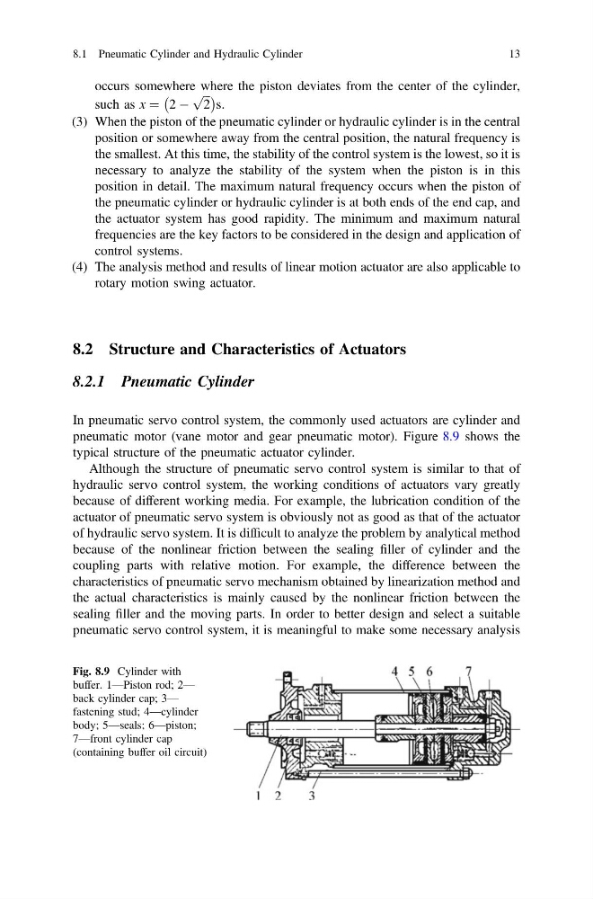
pneumatic motor (vane motor and gear pneumatic motor). Figure 8.9 shows the
typical structure of the pneumatic actuator cylinder.
Although the structure of pneumatic servo control system is similar to that of
hydraulic servo control system, the working conditions of actuators vary greatly
because of different working media. For example, the lubrication condition of the
actuator of pneumatic servo system is obviously not as good as that of the actuator
of hydraulic servo system. It is difficult to analyze the problem by analytical method
because of the nonlinear friction between the sealing filler of cylinder and the
coupling parts with relative motion. For example, the difference between the
characteristics of pneumatic servo mechanism obtained by linearization method and
the actual characteristics is mainly caused by the nonlinear friction between the
sealing filler and the moving parts. In order to better design and select a suitable
pneumatic servo control system, it is meaningful to make some necessary analysis
Fig. 8.9 Cylinder with
buffer. 1—Piston rod; 2—
back cylinder cap; 3—
fastening stud; 4—cylinder
body; 5—seals; 6—piston;
7—front cylinder cap
(containing buffer oil circuit)
8.1 Pneumatic Cylinder and Hydraulic Cylinder
13
such as x ¼ 2 À
ffiffi ffi
2
p
À
Á
s.
(3) When the piston of the pneumatic cylinder or hydraulic cylinder is in the central
position or somewhere away from the central position, the natural frequency is
the smallest. At this time, the stability of the control system is the lowest, so it is
necessary to analyze the stability of the system when the piston is in this
position in detail. The maximum natural frequency occurs when the piston of
the pneumatic cylinder or hydraulic cylinder is at both ends of the end cap, and
the actuator system has good rapidity. The minimum and maximum natural
frequencies are the key factors to be considered in the design and application of
control systems.
(4) The analysis method and results of linear motion actuator are also applicable to
rotary motion swing actuator.
8.2 Structure and Characteristics of Actuators
8.2.1 Pneumatic Cylinder
In pneumatic servo control system, the commonly used actuators are cylinder and
pneumatic motor (vane motor and gear pneumatic motor). Figure 8.9 shows the
typical structure of the pneumatic actuator cylinder.
Although the structure of pneumatic servo control system is similar to that of
hydraulic servo control system, the working conditions of actuators vary greatly
because of different working media. For example, the lubrication condition of the
actuator of pneumatic servo system is obviously not as good as that of the actuator
of hydraulic servo system. It is difficult to analyze the problem by analytical method
because of the nonlinear friction between the sealing filler of cylinder and the
coupling parts with relative motion. For example, the difference between the
characteristics of pneumatic servo mechanism obtained by linearization method and
the actual characteristics is mainly caused by the nonlinear friction between the
sealing filler and the moving parts. In order to better design and select a suitable
pneumatic servo control system, it is meaningful to make some necessary analysis
Fig. 8.9 Cylinder with
buffer. 1—Piston rod; 2—
back cylinder cap; 3—
fastening stud; 4—cylinder
body; 5—seals; 6—piston;
7—front cylinder cap
(containing buffer oil circuit)
8.1 Pneumatic Cylinder and Hydraulic Cylinder
13