

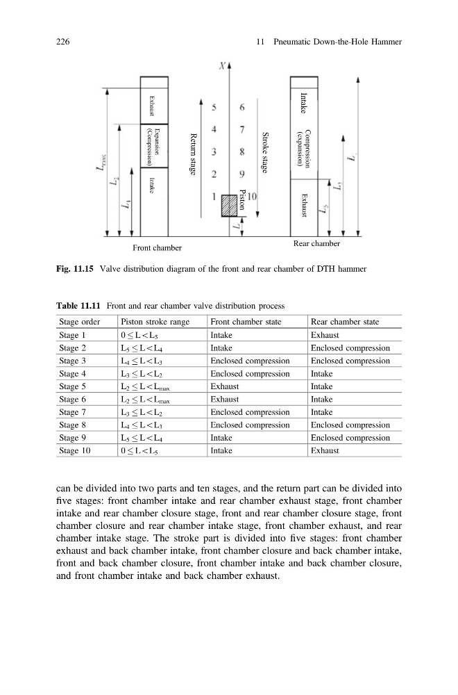
can be divided into two parts and ten stages, and the return part can be divided into
five stages: front chamber intake and rear chamber exhaust stage, front chamber
intake and rear chamber closure stage, front and rear chamber closure stage, front
chamber closure and rear chamber intake stage, front chamber exhaust, and rear
chamber intake stage. The stroke part is divided into five stages: front chamber
exhaust and back chamber intake, front chamber closure and back chamber intake,
front and back chamber closure, front chamber intake and back chamber closure,
and front chamber intake and back chamber exhaust.
Exhaust
Expansion
(Compression)
Intake
Intake
Compression
(expansion)
Exhaust
Stroke stage
Return stage
Piston
Front chamber
Rear chamber
Fig. 11.15 Valve distribution diagram of the front and rear chamber of DTH hammer
Table 11.11 Front and rear chamber valve distribution process
Stage order
Piston stroke range
Front chamber state
Rear chamber state
Stage 1
0 L\L 5
Intake
Exhaust
Stage 2
L 5 L\L 4
Intake
Enclosed compression
Stage 3
L 4 L\L 3
Enclosed compression
Enclosed compression
Stage 4
L 3 L\L 2
Enclosed compression
Intake
Stage 5
L 2 L\L max
Exhaust
Intake
Stage 6
L 2 L\L max
Exhaust
Intake
Stage 7
L 3 L\L 2
Enclosed compression
Intake
Stage 8
L 4 L\L 3
Enclosed compression
Enclosed compression
Stage 9
L 5 L\L 4
Intake
Enclosed compression
Stage 10
0 L\L 5
Intake
Exhaust
226
11 Pneumatic Down-the-Hole Hammer
five stages: front chamber intake and rear chamber exhaust stage, front chamber
intake and rear chamber closure stage, front and rear chamber closure stage, front
chamber closure and rear chamber intake stage, front chamber exhaust, and rear
chamber intake stage. The stroke part is divided into five stages: front chamber
exhaust and back chamber intake, front chamber closure and back chamber intake,
front and back chamber closure, front chamber intake and back chamber closure,
and front chamber intake and back chamber exhaust.
Exhaust
Expansion
(Compression)
Intake
Intake
Compression
(expansion)
Exhaust
Stroke stage
Return stage
Piston
Front chamber
Rear chamber
Fig. 11.15 Valve distribution diagram of the front and rear chamber of DTH hammer
Table 11.11 Front and rear chamber valve distribution process
Stage order
Piston stroke range
Front chamber state
Rear chamber state
Stage 1
0 L\L 5
Intake
Exhaust
Stage 2
L 5 L\L 4
Intake
Enclosed compression
Stage 3
L 4 L\L 3
Enclosed compression
Enclosed compression
Stage 4
L 3 L\L 2
Enclosed compression
Intake
Stage 5
L 2 L\L max
Exhaust
Intake
Stage 6
L 2 L\L max
Exhaust
Intake
Stage 7
L 3 L\L 2
Enclosed compression
Intake
Stage 8
L 4 L\L 3
Enclosed compression
Enclosed compression
Stage 9
L 5 L\L 4
Intake
Enclosed compression
Stage 10
0 L\L 5
Intake
Exhaust
226
11 Pneumatic Down-the-Hole Hammer