

where
p A ; p q
Air pressure of rear chamber and front chamber of cylinder;
V A ; V q
Working volume of rear chamber and front chamber of cylinder;
e 1 ; e 2 ; e 3 Intake, compression and exhaust power of rear chamber in stroke stage;
e 4 ; e 5 ; e 6 Exhaust power, compression power and intake power of front chamber in
stroke stage.
The intake power e 1 of the rear chamber in stroke is
e 1 ¼ p 1 V jk ¼ p 1 A k s jk
ð11:13Þ
where
p 1 Gas pressure (absolute pressure);
V jk Back chamber intake gas volume in stroke stage;
A k Working area of piston rear chamber;
s jk Inlet length of rear chamber in stroke stage.
The expansion work e 2 of the rear chamber in stroke stage is calculated in
adiabatic state. Then
e 2 ¼
p 1 V 1
K À 1
1 À
V 1
V 2
KÀ1
"
#
or e 2 ¼
p 1 V 1
K À 1
1 À
p 2
p 1
KÀ1
K
"
#
ð11:14Þ
where
p 1 ; p 2 Rear chamber pressure (absolute pressure) at the beginning and end of
expansion stage;
V 1 ; V 2 Volume of rear chamber at the beginning and end of expansion stage.
P Air absolute pressure/MPa
Rear chamber
Front chamber
Inlet
Inlet
Exhaust
Exhaust
Expand
Compress
Piston displacement/m
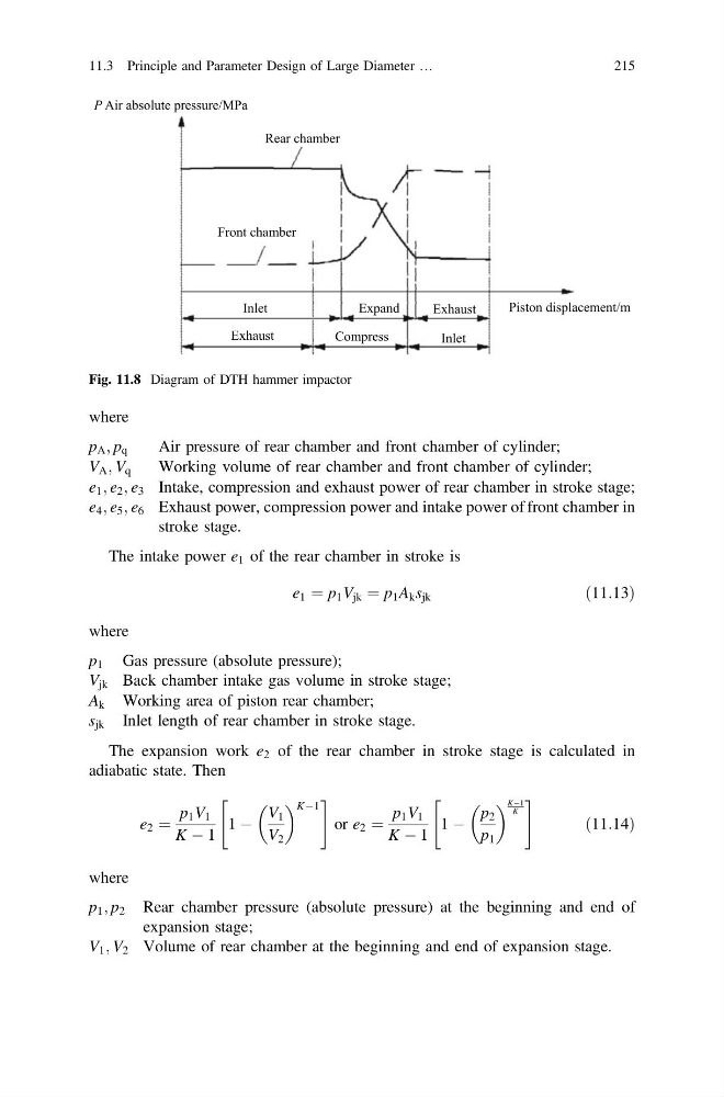
Fig. 11.8 Diagram of DTH hammer impactor
11.3 Principle and Parameter Design of Large Diameter …
215
p A ; p q
Air pressure of rear chamber and front chamber of cylinder;
V A ; V q
Working volume of rear chamber and front chamber of cylinder;
e 1 ; e 2 ; e 3 Intake, compression and exhaust power of rear chamber in stroke stage;
e 4 ; e 5 ; e 6 Exhaust power, compression power and intake power of front chamber in
stroke stage.
The intake power e 1 of the rear chamber in stroke is
e 1 ¼ p 1 V jk ¼ p 1 A k s jk
ð11:13Þ
where
p 1 Gas pressure (absolute pressure);
V jk Back chamber intake gas volume in stroke stage;
A k Working area of piston rear chamber;
s jk Inlet length of rear chamber in stroke stage.
The expansion work e 2 of the rear chamber in stroke stage is calculated in
adiabatic state. Then
e 2 ¼
p 1 V 1
K À 1
1 À
V 1
V 2
KÀ1
"
#
or e 2 ¼
p 1 V 1
K À 1
1 À
p 2
p 1
KÀ1
K
"
#
ð11:14Þ
where
p 1 ; p 2 Rear chamber pressure (absolute pressure) at the beginning and end of
expansion stage;
V 1 ; V 2 Volume of rear chamber at the beginning and end of expansion stage.
P Air absolute pressure/MPa
Rear chamber
Front chamber
Inlet
Inlet
Exhaust
Exhaust
Expand
Compress
Piston displacement/m
Fig. 11.8 Diagram of DTH hammer impactor
11.3 Principle and Parameter Design of Large Diameter …
215