

40:5 m
3
=min; the medium pressure is 14:0 kgf=cm
2 , the consumption of air is
60 m
3
=min; the high wind pressure is 17:6 kgf=cm
2 , the consumption of air is
85 m
3
=min.
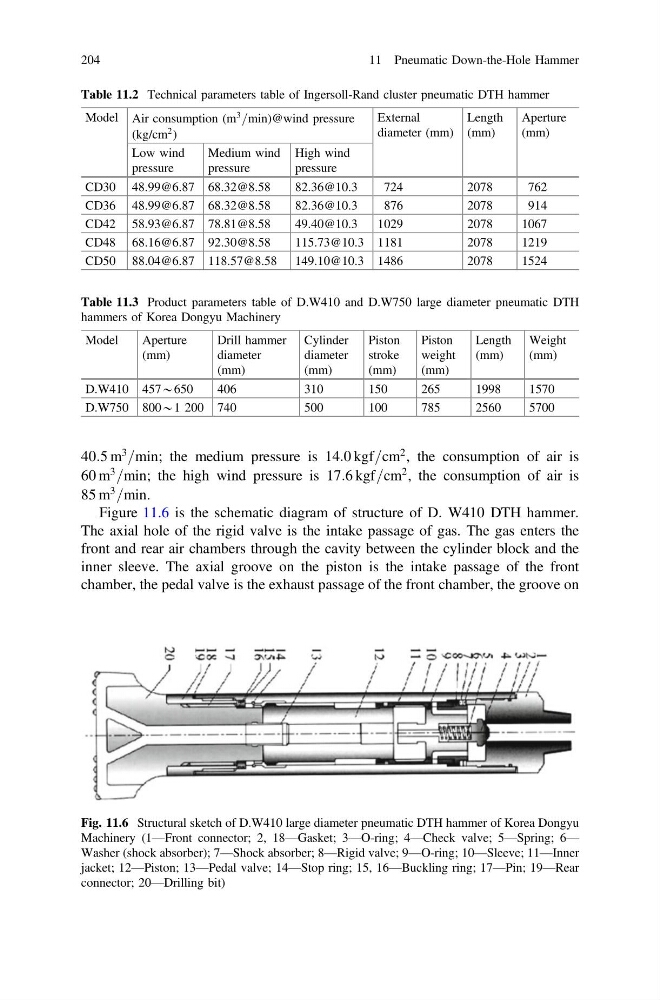
Figure 11.6 is the schematic diagram of structure of D. W410 DTH hammer.
The axial hole of the rigid valve is the intake passage of gas. The gas enters the
front and rear air chambers through the cavity between the cylinder block and the
inner sleeve. The axial groove on the piston is the intake passage of the front
chamber, the pedal valve is the exhaust passage of the front chamber, the groove on
Table 11.2 Technical parameters table of Ingersoll-Rand cluster pneumatic DTH hammer
Model Air consumption (m
3 =min)@wind pressure
(kg/cm
2 )
External
diameter (mm)
Length
(mm)
Aperture
(mm)
Low wind
pressure
Medium wind
pressure
High wind
pressure
CD30 48.99@6.87 68.32@8.58
82.36@10.3
724
2078
762
CD36 48.99@6.87 68.32@8.58
82.36@10.3
876
2078
914
CD42 58.93@6.87 78.81@8.58
49.40@10.3
1029
2078
1067
CD48 68.16@6.87 92.30@8.58
115.73@10.3 1181
2078
1219
CD50 88.04@6.87 118.57@8.58 149.10@10.3 1486
2078
1524
Table 11.3 Product parameters table of D.W410 and D.W750 large diameter pneumatic DTH
hammers of Korea Dongyu Machinery
Model
Aperture
(mm)
Drill hammer
diameter
(mm)
Cylinder
diameter
(mm)
Piston
stroke
(mm)
Piston
weight
(mm)
Length
(mm)
Weight
(mm)
D.W410 457*650
406
310
150
265
1998
1570
D.W750 800*1 200 740
500
100
785
2560
5700
Fig. 11.6 Structural sketch of D.W410 large diameter pneumatic DTH hammer of Korea Dongyu
Machinery (1—Front connector; 2, 18—Gasket; 3—O-ring; 4—Check valve; 5—Spring; 6—
Washer (shock absorber); 7—Shock absorber; 8—Rigid valve; 9—O-ring; 10—Sleeve; 11—Inner
jacket; 12—Piston; 13—Pedal valve; 14—Stop ring; 15, 16—Buckling ring; 17—Pin; 19—Rear
connector; 20—Drilling bit)
204
11 Pneumatic Down-the-Hole Hammer
3
=min; the medium pressure is 14:0 kgf=cm
2 , the consumption of air is
60 m
3
=min; the high wind pressure is 17:6 kgf=cm
2 , the consumption of air is
85 m
3
=min.
Figure 11.6 is the schematic diagram of structure of D. W410 DTH hammer.
The axial hole of the rigid valve is the intake passage of gas. The gas enters the
front and rear air chambers through the cavity between the cylinder block and the
inner sleeve. The axial groove on the piston is the intake passage of the front
chamber, the pedal valve is the exhaust passage of the front chamber, the groove on
Table 11.2 Technical parameters table of Ingersoll-Rand cluster pneumatic DTH hammer
Model Air consumption (m
3 =min)@wind pressure
(kg/cm
2 )
External
diameter (mm)
Length
(mm)
Aperture
(mm)
Low wind
pressure
Medium wind
pressure
High wind
pressure
CD30 48.99@6.87 68.32@8.58
82.36@10.3
724
2078
762
CD36 48.99@6.87 68.32@8.58
82.36@10.3
876
2078
914
CD42 58.93@6.87 78.81@8.58
49.40@10.3
1029
2078
1067
CD48 68.16@6.87 92.30@8.58
115.73@10.3 1181
2078
1219
CD50 88.04@6.87 118.57@8.58 149.10@10.3 1486
2078
1524
Table 11.3 Product parameters table of D.W410 and D.W750 large diameter pneumatic DTH
hammers of Korea Dongyu Machinery
Model
Aperture
(mm)
Drill hammer
diameter
(mm)
Cylinder
diameter
(mm)
Piston
stroke
(mm)
Piston
weight
(mm)
Length
(mm)
Weight
(mm)
D.W410 457*650
406
310
150
265
1998
1570
D.W750 800*1 200 740
500
100
785
2560
5700
Fig. 11.6 Structural sketch of D.W410 large diameter pneumatic DTH hammer of Korea Dongyu
Machinery (1—Front connector; 2, 18—Gasket; 3—O-ring; 4—Check valve; 5—Spring; 6—
Washer (shock absorber); 7—Shock absorber; 8—Rigid valve; 9—O-ring; 10—Sleeve; 11—Inner
jacket; 12—Piston; 13—Pedal valve; 14—Stop ring; 15, 16—Buckling ring; 17—Pin; 19—Rear
connector; 20—Drilling bit)
204
11 Pneumatic Down-the-Hole Hammer