

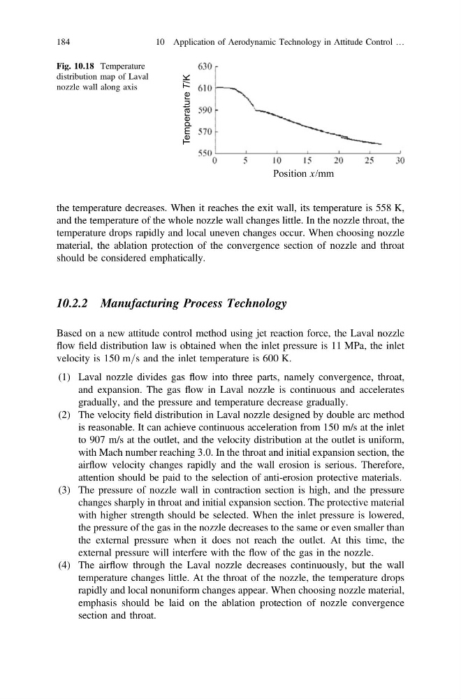
the temperature decreases. When it reaches the exit wall, its temperature is 558 K,
and the temperature of the whole nozzle wall changes little. In the nozzle throat, the
temperature drops rapidly and local uneven changes occur. When choosing nozzle
material, the ablation protection of the convergence section of nozzle and throat
should be considered emphatically.
10.2.2 Manufacturing Process Technology
Based on a new attitude control method using jet reaction force, the Laval nozzle
flow field distribution law is obtained when the inlet pressure is 11 MPa, the inlet
velocity is 150 m=s and the inlet temperature is 600 K.
(1) Laval nozzle divides gas flow into three parts, namely convergence, throat,
and expansion. The gas flow in Laval nozzle is continuous and accelerates
gradually, and the pressure and temperature decrease gradually.
(2) The velocity field distribution in Laval nozzle designed by double arc method
is reasonable. It can achieve continuous acceleration from 150 m/s at the inlet
to 907 m/s at the outlet, and the velocity distribution at the outlet is uniform,
with Mach number reaching 3.0. In the throat and initial expansion section, the
airflow velocity changes rapidly and the wall erosion is serious. Therefore,
attention should be paid to the selection of anti-erosion protective materials.
(3) The pressure of nozzle wall in contraction section is high, and the pressure
changes sharply in throat and initial expansion section. The protective material
with higher strength should be selected. When the inlet pressure is lowered,
the pressure of the gas in the nozzle decreases to the same or even smaller than
the external pressure when it does not reach the outlet. At this time, the
external pressure will interfere with the flow of the gas in the nozzle.
(4) The airflow through the Laval nozzle decreases continuously, but the wall
temperature changes little. At the throat of the nozzle, the temperature drops
rapidly and local nonuniform changes appear. When choosing nozzle material,
emphasis should be laid on the ablation protection of nozzle convergence
section and throat.
Position x/mm
Temperature T/K
Fig. 10.18 Temperature
distribution map of Laval
nozzle wall along axis
184
10 Application of Aerodynamic Technology in Attitude Control …
and the temperature of the whole nozzle wall changes little. In the nozzle throat, the
temperature drops rapidly and local uneven changes occur. When choosing nozzle
material, the ablation protection of the convergence section of nozzle and throat
should be considered emphatically.
10.2.2 Manufacturing Process Technology
Based on a new attitude control method using jet reaction force, the Laval nozzle
flow field distribution law is obtained when the inlet pressure is 11 MPa, the inlet
velocity is 150 m=s and the inlet temperature is 600 K.
(1) Laval nozzle divides gas flow into three parts, namely convergence, throat,
and expansion. The gas flow in Laval nozzle is continuous and accelerates
gradually, and the pressure and temperature decrease gradually.
(2) The velocity field distribution in Laval nozzle designed by double arc method
is reasonable. It can achieve continuous acceleration from 150 m/s at the inlet
to 907 m/s at the outlet, and the velocity distribution at the outlet is uniform,
with Mach number reaching 3.0. In the throat and initial expansion section, the
airflow velocity changes rapidly and the wall erosion is serious. Therefore,
attention should be paid to the selection of anti-erosion protective materials.
(3) The pressure of nozzle wall in contraction section is high, and the pressure
changes sharply in throat and initial expansion section. The protective material
with higher strength should be selected. When the inlet pressure is lowered,
the pressure of the gas in the nozzle decreases to the same or even smaller than
the external pressure when it does not reach the outlet. At this time, the
external pressure will interfere with the flow of the gas in the nozzle.
(4) The airflow through the Laval nozzle decreases continuously, but the wall
temperature changes little. At the throat of the nozzle, the temperature drops
rapidly and local nonuniform changes appear. When choosing nozzle material,
emphasis should be laid on the ablation protection of nozzle convergence
section and throat.
Position x/mm
Temperature T/K
Fig. 10.18 Temperature
distribution map of Laval
nozzle wall along axis
184
10 Application of Aerodynamic Technology in Attitude Control …