

pressure relief valves, and so on. The throttle orifice plate is installed in the connecting joint of the experimental cabin. High-pressure cold air enters the reversing
valve through the pipeline, transfer tooling, and intake pipe, and sprays the cold air
through the outlet pipe. The experimental cabin is installed on the horizontal slide
platform and connected with the thrust sensor through the tooling. The thrust generated by the ejected cooling gas is transmitted to the thrust sensor through the
reaction force. The signal amplifier amplifies the signal of the thrust sensor and
outputs it to the data acquisition computer for acquisition and monitoring.
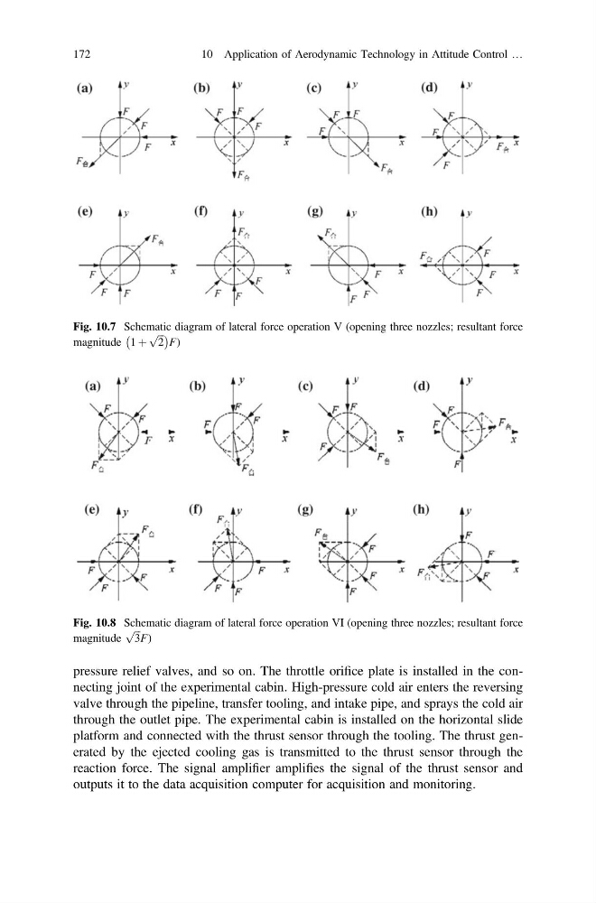
Fig. 10.7 Schematic diagram of lateral force operation V (opening three nozzles; resultant force
magnitude 1 þ
ffiffi ffi
2
p
À
Á
F)
Fig. 10.8 Schematic diagram of lateral force operation VI (opening three nozzles; resultant force
magnitude
ffiffi ffi
3
p
F)
172
10 Application of Aerodynamic Technology in Attitude Control …
valve through the pipeline, transfer tooling, and intake pipe, and sprays the cold air
through the outlet pipe. The experimental cabin is installed on the horizontal slide
platform and connected with the thrust sensor through the tooling. The thrust generated by the ejected cooling gas is transmitted to the thrust sensor through the
reaction force. The signal amplifier amplifies the signal of the thrust sensor and
outputs it to the data acquisition computer for acquisition and monitoring.
Fig. 10.7 Schematic diagram of lateral force operation V (opening three nozzles; resultant force
magnitude 1 þ
ffiffi ffi
2
p
À
Á
F)
Fig. 10.8 Schematic diagram of lateral force operation VI (opening three nozzles; resultant force
magnitude
ffiffi ffi
3
p
F)
172
10 Application of Aerodynamic Technology in Attitude Control …