

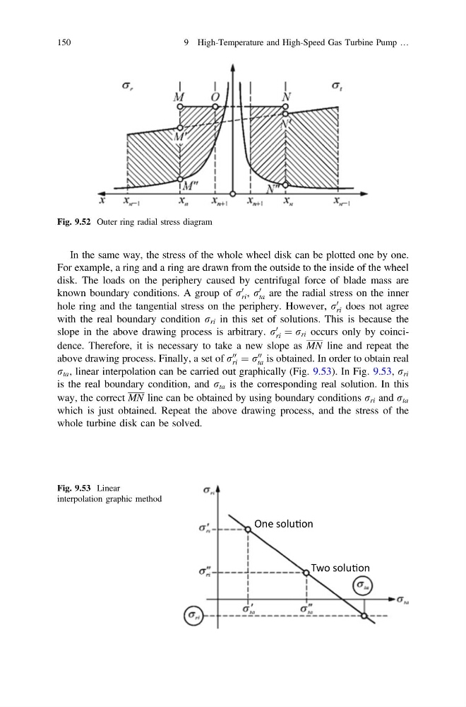
In the same way, the stress of the whole wheel disk can be plotted one by one.
For example, a ring and a ring are drawn from the outside to the inside of the wheel
disk. The loads on the periphery caused by centrifugal force of blade mass are
known boundary conditions. A group of r
0
ri , r
0
ta are the radial stress on the inner
hole ring and the tangential stress on the periphery. However, r
0
ri does not agree
with the real boundary condition r ri in this set of solutions. This is because the
slope in the above drawing process is arbitrary. r
0
ri ¼ r ri occurs only by coincidence. Therefore, it is necessary to take a new slope as MN line and repeat the
above drawing process. Finally, a set of r
00
ri ¼ r
00
ta is obtained. In order to obtain real
r ta , linear interpolation can be carried out graphically (Fig. 9.53). In Fig. 9.53, r ri
is the real boundary condition, and r ta is the corresponding real solution. In this
way, the correct MN line can be obtained by using boundary conditions r ri and r ta
which is just obtained. Repeat the above drawing process, and the stress of the
whole turbine disk can be solved.
Fig. 9.52 Outer ring radial stress diagram
One soluƟon
Two soluƟon
Fig. 9.53 Linear
interpolation graphic method
150
9 High-Temperature and High-Speed Gas Turbine Pump …
For example, a ring and a ring are drawn from the outside to the inside of the wheel
disk. The loads on the periphery caused by centrifugal force of blade mass are
known boundary conditions. A group of r
0
ri , r
0
ta are the radial stress on the inner
hole ring and the tangential stress on the periphery. However, r
0
ri does not agree
with the real boundary condition r ri in this set of solutions. This is because the
slope in the above drawing process is arbitrary. r
0
ri ¼ r ri occurs only by coincidence. Therefore, it is necessary to take a new slope as MN line and repeat the
above drawing process. Finally, a set of r
00
ri ¼ r
00
ta is obtained. In order to obtain real
r ta , linear interpolation can be carried out graphically (Fig. 9.53). In Fig. 9.53, r ri
is the real boundary condition, and r ta is the corresponding real solution. In this
way, the correct MN line can be obtained by using boundary conditions r ri and r ta
which is just obtained. Repeat the above drawing process, and the stress of the
whole turbine disk can be solved.
Fig. 9.52 Outer ring radial stress diagram
One soluƟon
Two soluƟon
Fig. 9.53 Linear
interpolation graphic method
150
9 High-Temperature and High-Speed Gas Turbine Pump …