

1000
2000
3000
4000
5000
6000
10
0
20
30
40
50
60
70
Engine torque (Nm)
Optimal operation line (OOL)
220
230
240
250
350
210
210
Fuel consumption (g/kWh)
300
220
Wide open throttle (WOT)
Engine speed (rpm)
379
Hybrid Vehicles
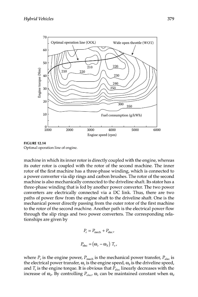
Figure 12.14
Optimal operation line of engine.
machine in which its inner rotor is directly coupled with the engine, whereas
its outer rotor is coupled with the rotor of the second machine. The inner
rotor of the first machine has a three-phase winding, which is connected to
a power converter via slip rings and carbon brushes. The rotor of the second
machine is also mechanically connected to the driveline shaft. Its stator has a
three-phase winding that is fed by another power converter. The two power
converters are electrically connected via a DC link. Thus, there are two
paths of power flow from the engine shaft to the driveline shaft. One is the
mechanical power directly passing from the outer rotor of the first machine
to the rotor of the second machine. Another path is the electrical power flow
through the slip rings and two power converters. The corresponding relationships are given by
P = P
P
e
mech + elec ,
P = (ω − ω ) T e ,
elec
e
d
where P e is the engine power, P mech is the mechanical power transfer, P elec is
the electrical power transfer, ω e is the engine speed, ω d is the driveline speed,
and T e is the engine torque. It is obvious that P elec linearly decreases with the
increase of ω d . By controlling P elec , ω e can be maintained constant when ω d
2000
3000
4000
5000
6000
10
0
20
30
40
50
60
70
Engine torque (Nm)
Optimal operation line (OOL)
220
230
240
250
350
210
210
Fuel consumption (g/kWh)
300
220
Wide open throttle (WOT)
Engine speed (rpm)
379
Hybrid Vehicles
Figure 12.14
Optimal operation line of engine.
machine in which its inner rotor is directly coupled with the engine, whereas
its outer rotor is coupled with the rotor of the second machine. The inner
rotor of the first machine has a three-phase winding, which is connected to
a power converter via slip rings and carbon brushes. The rotor of the second
machine is also mechanically connected to the driveline shaft. Its stator has a
three-phase winding that is fed by another power converter. The two power
converters are electrically connected via a DC link. Thus, there are two
paths of power flow from the engine shaft to the driveline shaft. One is the
mechanical power directly passing from the outer rotor of the first machine
to the rotor of the second machine. Another path is the electrical power flow
through the slip rings and two power converters. The corresponding relationships are given by
P = P
P
e
mech + elec ,
P = (ω − ω ) T e ,
elec
e
d
where P e is the engine power, P mech is the mechanical power transfer, P elec is
the electrical power transfer, ω e is the engine speed, ω d is the driveline speed,
and T e is the engine torque. It is obvious that P elec linearly decreases with the
increase of ω d . By controlling P elec , ω e can be maintained constant when ω d