

Fuel Cells
337
Feedback from
vehicle
System
control and
monitoring
Hydrogen-rich gas
+
Air
Fuel cell
stack
DC
voltage
Power
conditioner
Power to
vehicle
loads
Water
Air
Fuel
Fuel
processor
Exhaust heat
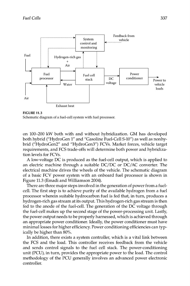
Figure 11.3
Schematic diagram of a fuel-cell system with fuel processor.
on 100–200 kW both with and without hybridization. GM has developed
both hybrid (“HydroGen 1” and “Gasoline Fuel-Cell S-10”) as well as nonhybrid (“HydroGen2” and “HydroGen3”) FCVs. Market forces, vehicle target
requirements, and FCS trade-offs will determine both power and hybridization levels for FCVs.
A low-voltage DC is produced as the fuel-cell output, which is applied to
an electric machine through a suitable DC/DC or DC/AC converter. The
electrical machine drives the wheels of the vehicle. The schematic diagram
of a basic FCV power system with an onboard fuel processor is shown in
Figure 11.3 (Emadi and Williamson 2004).
There are three major steps involved in the generation of power from a fuelcell. The first step is to achieve purity of the available hydrogen from a fuel
processor wherein suitable hydrocarbon fuel is fed that, in turn, produces a
hydrogen-rich gas stream at its output. This hydrogen-rich gas stream is then
fed to the anode of the fuel-cell. The generation of the DC voltage through
the fuel-cell makes up the second stage of the power-processing unit. Lastly,
the power output needs to be properly harnessed, which is achieved through
an appropriate power conditioner. Ideally, the power conditioner must have
minimal losses for higher efficiency. Power conditioning efficiencies can typically be higher than 80%.
In addition, there exists a system controller, which is a vital link between
the FCS and the load. This controller receives feedback from the vehicle
and sends control signals to the fuel cell stack. The power-conditioning
unit (PCU), in turn, provides the appropriate power to the load. The control
methodology of the PCU generally involves an advanced power electronic
controller.
337
Feedback from
vehicle
System
control and
monitoring
Hydrogen-rich gas
+
Air
Fuel cell
stack
DC
voltage
Power
conditioner
Power to
vehicle
loads
Water
Air
Fuel
Fuel
processor
Exhaust heat
Figure 11.3
Schematic diagram of a fuel-cell system with fuel processor.
on 100–200 kW both with and without hybridization. GM has developed
both hybrid (“HydroGen 1” and “Gasoline Fuel-Cell S-10”) as well as nonhybrid (“HydroGen2” and “HydroGen3”) FCVs. Market forces, vehicle target
requirements, and FCS trade-offs will determine both power and hybridization levels for FCVs.
A low-voltage DC is produced as the fuel-cell output, which is applied to
an electric machine through a suitable DC/DC or DC/AC converter. The
electrical machine drives the wheels of the vehicle. The schematic diagram
of a basic FCV power system with an onboard fuel processor is shown in
Figure 11.3 (Emadi and Williamson 2004).
There are three major steps involved in the generation of power from a fuelcell. The first step is to achieve purity of the available hydrogen from a fuel
processor wherein suitable hydrocarbon fuel is fed that, in turn, produces a
hydrogen-rich gas stream at its output. This hydrogen-rich gas stream is then
fed to the anode of the fuel-cell. The generation of the DC voltage through
the fuel-cell makes up the second stage of the power-processing unit. Lastly,
the power output needs to be properly harnessed, which is achieved through
an appropriate power conditioner. Ideally, the power conditioner must have
minimal losses for higher efficiency. Power conditioning efficiencies can typically be higher than 80%.
In addition, there exists a system controller, which is a vital link between
the FCS and the load. This controller receives feedback from the vehicle
and sends control signals to the fuel cell stack. The power-conditioning
unit (PCU), in turn, provides the appropriate power to the load. The control
methodology of the PCU generally involves an advanced power electronic
controller.