

CO
2
2
1500
14
12
10
8
6
4
, CO and O (%vol.)
2
0
2000
2500
3000
3500
4000
4500
5000
5500
Engine speed (rpm)
CO , CO and O concentration vs. engine speed at WOT
2
2
CO concentration with gasoline
CO concentration with CNG
2
2
CO concentration with CNG
O concentration with gasoline
2
CO concentration with gasoline
O concentration with CNG
2
237
Compressed Natural Gas
8.6.1 Natural gas in Si engines
Aslam et al. (2006) converted gasoline engines into bi-fuel engines, converted
to a computer integrated bi-fueling system from a gasoline engine, and was
operated separately either with gasoline or CNG using an electronically controlled solenoid actuated valve system. CNG was stored under a maximum
pressure of 200 bars.
Before entering into the carburetor, CNG passes through the three-stage
conversion kit. The conversion kit supplies CNG to the engine carburetor
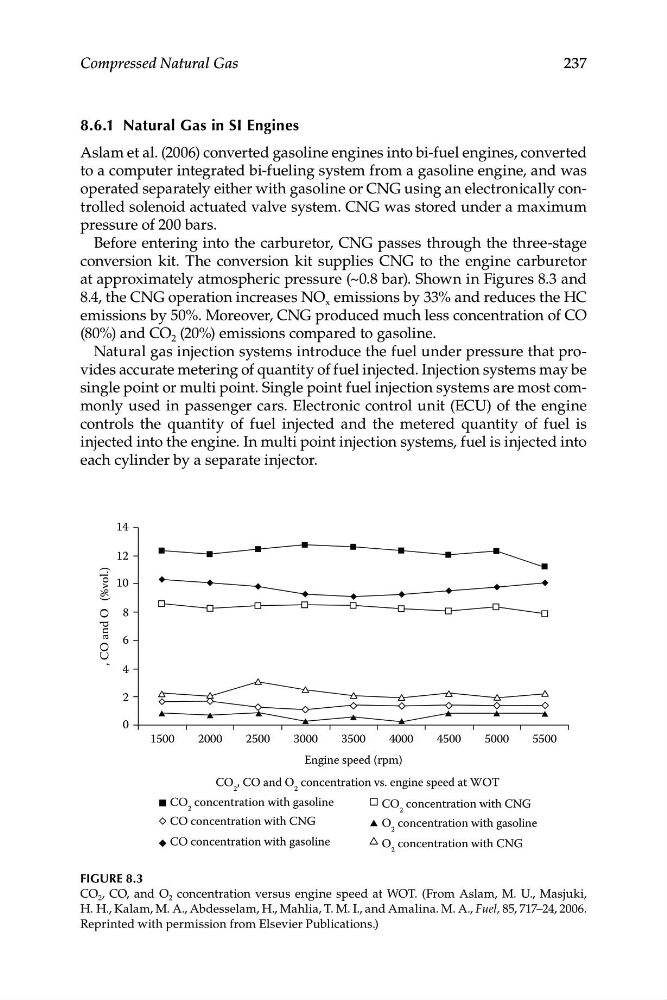
at approximately atmospheric pressure (~0.8 bar). Shown in Figures 8.3 and
8.4, the CNG operation increases NO x emissions by 33% and reduces the HC
emissions by 50%. Moreover, CNG produced much less concentration of CO
(80%) and CO 2 (20%) emissions compared to gasoline.
Natural gas injection systems introduce the fuel under pressure that provides accurate metering of quantity of fuel injected. Injection systems may be
single point or multi point. Single point fuel injection systems are most commonly used in passenger cars. Electronic control unit (ECU) of the engine
controls the quantity of fuel injected and the metered quantity of fuel is
injected into the engine. In multi point injection systems, fuel is injected into
each cylinder by a separate injector.
Figure 8.3
CO 2 , CO, and O 2 concentration versus engine speed at WOT. (From Aslam, M. U., Masjuki,
H. H., Kalam, M. A., Abdesselam, H., Mahlia, T. M. I., and Amalina. M. A., Fuel, 85, 717–24, 2006.
Reprinted with permission from Elsevier Publications.)
2
2
1500
14
12
10
8
6
4
, CO and O (%vol.)
2
0
2000
2500
3000
3500
4000
4500
5000
5500
Engine speed (rpm)
CO , CO and O concentration vs. engine speed at WOT
2
2
CO concentration with gasoline
CO concentration with CNG
2
2
CO concentration with CNG
O concentration with gasoline
2
CO concentration with gasoline
O concentration with CNG
2
237
Compressed Natural Gas
8.6.1 Natural gas in Si engines
Aslam et al. (2006) converted gasoline engines into bi-fuel engines, converted
to a computer integrated bi-fueling system from a gasoline engine, and was
operated separately either with gasoline or CNG using an electronically controlled solenoid actuated valve system. CNG was stored under a maximum
pressure of 200 bars.
Before entering into the carburetor, CNG passes through the three-stage
conversion kit. The conversion kit supplies CNG to the engine carburetor
at approximately atmospheric pressure (~0.8 bar). Shown in Figures 8.3 and
8.4, the CNG operation increases NO x emissions by 33% and reduces the HC
emissions by 50%. Moreover, CNG produced much less concentration of CO
(80%) and CO 2 (20%) emissions compared to gasoline.
Natural gas injection systems introduce the fuel under pressure that provides accurate metering of quantity of fuel injected. Injection systems may be
single point or multi point. Single point fuel injection systems are most commonly used in passenger cars. Electronic control unit (ECU) of the engine
controls the quantity of fuel injected and the metered quantity of fuel is
injected into the engine. In multi point injection systems, fuel is injected into
each cylinder by a separate injector.
Figure 8.3
CO 2 , CO, and O 2 concentration versus engine speed at WOT. (From Aslam, M. U., Masjuki,
H. H., Kalam, M. A., Abdesselam, H., Mahlia, T. M. I., and Amalina. M. A., Fuel, 85, 717–24, 2006.
Reprinted with permission from Elsevier Publications.)