

6 Tool Model Building and Research on Cutting Simulation …
61
6.2 Milling Finite Element Model
6.2.1 Establishment of Cutting Simulation Model
In this study, the edge burr formation of Ti6Al4V under high-speed micro-milling is
studied using Abaqus. Firstly, the geometric models of the workpiece and tool were
established in CATIA.
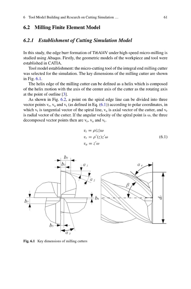
Tool model establishment: the micro-cutting tool of the integral end milling cutter
was selected for the simulation. The key dimensions of the milling cutter are shown
in Fig. 6.1.
The helix edge of the milling cutter can be defined as a helix which is composed
of the helix motion with the axis of the center axis of the cutter as the rotating axis
at the point of outline [3].
As shown in Fig. 6.2, a point on the spiral edge line can be divided into three
vector points v r , v a and v t (as defined in Eq. (6.1)) according to polar coordinates, in
which v t is tangential vector of the spiral line, v a is axial vector of the cutter, and v r
is radial vector of the cutter. If the angular velocity of the spiral point is ω, the three
decomposed vector points then are v r , v a and v t .
v t = ρ(z)ω
v r = ρ
(z)z
ω
v a = z
ω
(6.1)
Fig. 6.1 Key dimensions of milling cutters
61
6.2 Milling Finite Element Model
6.2.1 Establishment of Cutting Simulation Model
In this study, the edge burr formation of Ti6Al4V under high-speed micro-milling is
studied using Abaqus. Firstly, the geometric models of the workpiece and tool were
established in CATIA.
Tool model establishment: the micro-cutting tool of the integral end milling cutter
was selected for the simulation. The key dimensions of the milling cutter are shown
in Fig. 6.1.
The helix edge of the milling cutter can be defined as a helix which is composed
of the helix motion with the axis of the center axis of the cutter as the rotating axis
at the point of outline [3].
As shown in Fig. 6.2, a point on the spiral edge line can be divided into three
vector points v r , v a and v t (as defined in Eq. (6.1)) according to polar coordinates, in
which v t is tangential vector of the spiral line, v a is axial vector of the cutter, and v r
is radial vector of the cutter. If the angular velocity of the spiral point is ω, the three
decomposed vector points then are v r , v a and v t .
v t = ρ(z)ω
v r = ρ
(z)z
ω
v a = z
ω
(6.1)
Fig. 6.1 Key dimensions of milling cutters