

18 The Effect of Surface Ultrasonic Rolling Processing …
233
Table 18.4 Typical values of
the contact fatigue life of
samples at different static
rolling loads
Static rolling
load/(N)
Rated life
(L10)
[×10 6 ]
Median life
(L50)
[×10 6 ]
Characteristic
life (L63.2)
[×10 6 ]
Untreated
0.2134
0.9138
1.5249
600
0.6432
2.5846
4.1529
800
0.9645
4.1137
5.1707
1000
1.3758
8.1428
11.2821
1200
0.7957
4.7138
6.6501
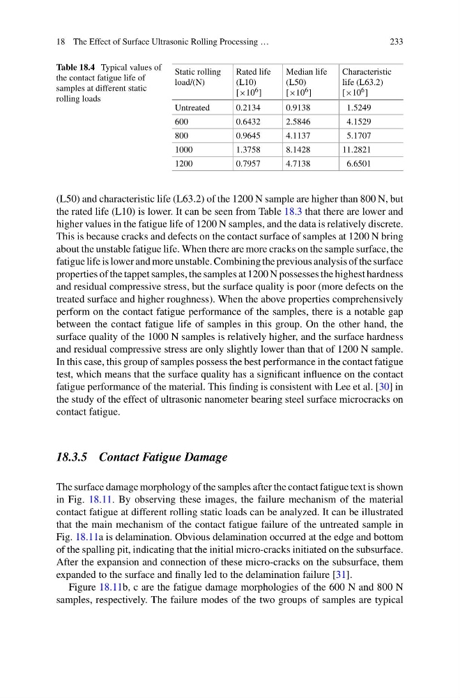
(L50) and characteristic life (L63.2) of the 1200 N sample are higher than 800 N, but
the rated life (L10) is lower. It can be seen from Table 18.3 that there are lower and
higher values in the fatigue life of 1200 N samples, and the data is relatively discrete.
This is because cracks and defects on the contact surface of samples at 1200 N bring
about the unstable fatigue life. When there are more cracks on the sample surface, the
fatigue life is lower and more unstable. Combining the previous analysis of the surface
properties of the tappet samples, the samples at 1200 N possesses the highest hardness
and residual compressive stress, but the surface quality is poor (more defects on the
treated surface and higher roughness). When the above properties comprehensively
perform on the contact fatigue performance of the samples, there is a notable gap
between the contact fatigue life of samples in this group. On the other hand, the
surface quality of the 1000 N samples is relatively higher, and the surface hardness
and residual compressive stress are only slightly lower than that of 1200 N sample.
In this case, this group of samples possess the best performance in the contact fatigue
test, which means that the surface quality has a significant influence on the contact
fatigue performance of the material. This finding is consistent with Lee et al. [30] in
the study of the effect of ultrasonic nanometer bearing steel surface microcracks on
contact fatigue.
18.3.5 Contact Fatigue Damage
The surface damage morphology of the samples after the contact fatigue text is shown
in Fig. 18.11. By observing these images, the failure mechanism of the material
contact fatigue at different rolling static loads can be analyzed. It can be illustrated
that the main mechanism of the contact fatigue failure of the untreated sample in
Fig. 18.11a is delamination. Obvious delamination occurred at the edge and bottom
of the spalling pit, indicating that the initial micro-cracks initiated on the subsurface.
After the expansion and connection of these micro-cracks on the subsurface, them
expanded to the surface and finally led to the delamination failure [31].
Figure 18.11b, c are the fatigue damage morphologies of the 600 N and 800 N
samples, respectively. The failure modes of the two groups of samples are typical
233
Table 18.4 Typical values of
the contact fatigue life of
samples at different static
rolling loads
Static rolling
load/(N)
Rated life
(L10)
[×10 6 ]
Median life
(L50)
[×10 6 ]
Characteristic
life (L63.2)
[×10 6 ]
Untreated
0.2134
0.9138
1.5249
600
0.6432
2.5846
4.1529
800
0.9645
4.1137
5.1707
1000
1.3758
8.1428
11.2821
1200
0.7957
4.7138
6.6501
(L50) and characteristic life (L63.2) of the 1200 N sample are higher than 800 N, but
the rated life (L10) is lower. It can be seen from Table 18.3 that there are lower and
higher values in the fatigue life of 1200 N samples, and the data is relatively discrete.
This is because cracks and defects on the contact surface of samples at 1200 N bring
about the unstable fatigue life. When there are more cracks on the sample surface, the
fatigue life is lower and more unstable. Combining the previous analysis of the surface
properties of the tappet samples, the samples at 1200 N possesses the highest hardness
and residual compressive stress, but the surface quality is poor (more defects on the
treated surface and higher roughness). When the above properties comprehensively
perform on the contact fatigue performance of the samples, there is a notable gap
between the contact fatigue life of samples in this group. On the other hand, the
surface quality of the 1000 N samples is relatively higher, and the surface hardness
and residual compressive stress are only slightly lower than that of 1200 N sample.
In this case, this group of samples possess the best performance in the contact fatigue
test, which means that the surface quality has a significant influence on the contact
fatigue performance of the material. This finding is consistent with Lee et al. [30] in
the study of the effect of ultrasonic nanometer bearing steel surface microcracks on
contact fatigue.
18.3.5 Contact Fatigue Damage
The surface damage morphology of the samples after the contact fatigue text is shown
in Fig. 18.11. By observing these images, the failure mechanism of the material
contact fatigue at different rolling static loads can be analyzed. It can be illustrated
that the main mechanism of the contact fatigue failure of the untreated sample in
Fig. 18.11a is delamination. Obvious delamination occurred at the edge and bottom
of the spalling pit, indicating that the initial micro-cracks initiated on the subsurface.
After the expansion and connection of these micro-cracks on the subsurface, them
expanded to the surface and finally led to the delamination failure [31].
Figure 18.11b, c are the fatigue damage morphologies of the 600 N and 800 N
samples, respectively. The failure modes of the two groups of samples are typical