

158
X. Bi et al.
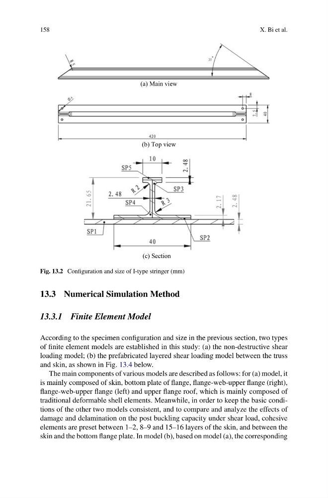
(a) Main view
(b) Top view
(c) Section
Fig. 13.2 Configuration and size of I-type stringer (mm)
13.3 Numerical Simulation Method
13.3.1 Finite Element Model
According to the specimen configuration and size in the previous section, two types
of finite element models are established in this study: (a) the non-destructive shear
loading model; (b) the prefabricated layered shear loading model between the truss
and skin, as shown in Fig. 13.4 below.
The main components of various models are described as follows: for (a) model, it
is mainly composed of skin, bottom plate of flange, flange-web-upper flange (right),
flange-web-upper flange (left) and upper flange roof, which is mainly composed of
traditional deformable shell elements. Meanwhile, in order to keep the basic conditions of the other two models consistent, and to compare and analyze the effects of
damage and delamination on the post buckling capacity under shear load, cohesive
elements are preset between 1–2, 8–9 and 15–16 layers of the skin, and between the
skin and the bottom flange plate. In model (b), based on model (a), the corresponding
X. Bi et al.
(a) Main view
(b) Top view
(c) Section
Fig. 13.2 Configuration and size of I-type stringer (mm)
13.3 Numerical Simulation Method
13.3.1 Finite Element Model
According to the specimen configuration and size in the previous section, two types
of finite element models are established in this study: (a) the non-destructive shear
loading model; (b) the prefabricated layered shear loading model between the truss
and skin, as shown in Fig. 13.4 below.
The main components of various models are described as follows: for (a) model, it
is mainly composed of skin, bottom plate of flange, flange-web-upper flange (right),
flange-web-upper flange (left) and upper flange roof, which is mainly composed of
traditional deformable shell elements. Meanwhile, in order to keep the basic conditions of the other two models consistent, and to compare and analyze the effects of
damage and delamination on the post buckling capacity under shear load, cohesive
elements are preset between 1–2, 8–9 and 15–16 layers of the skin, and between the
skin and the bottom flange plate. In model (b), based on model (a), the corresponding