

148
Z. Liu et al.
Fig. 12.5 Mises equivalent
stress distribution under load
case 2
linearized on a stress component basis to produce membrane and bending stresses.
Membrane and bending stresses are developed on cross sections through the thickness
of a component. Therefore, Stress Classification Lines (SCLs) should be specified
orienting normal to contour lines of the stress component of highest magnitude.
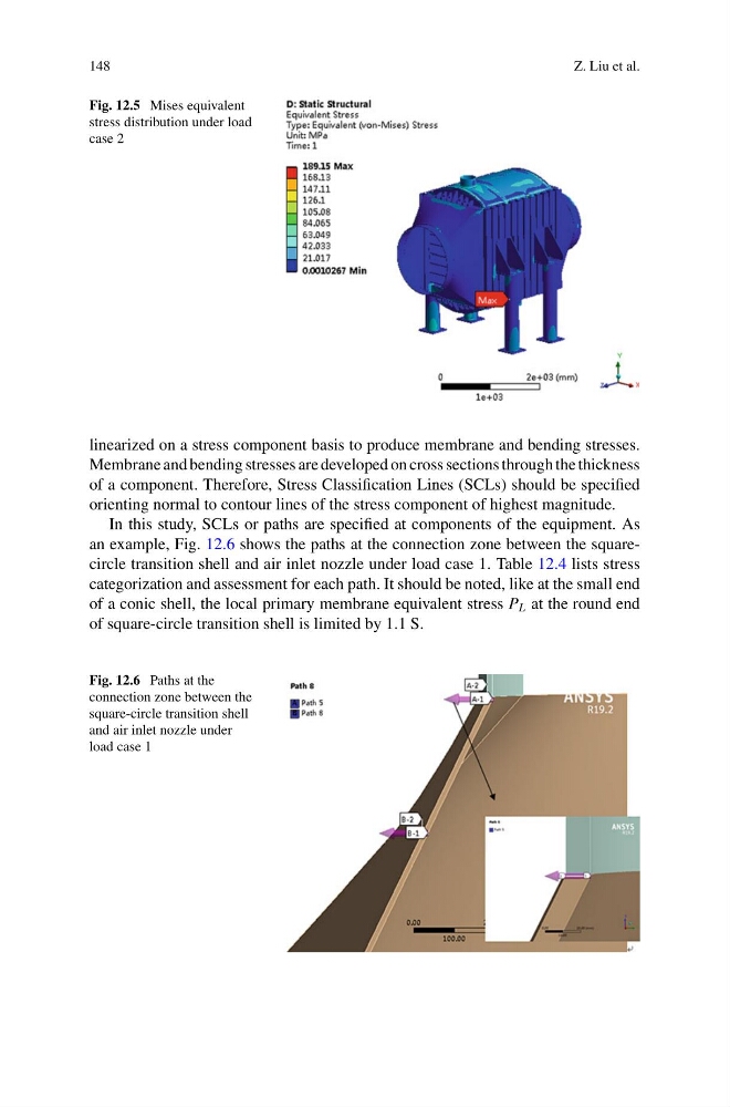
In this study, SCLs or paths are specified at components of the equipment. As
an example, Fig. 12.6 shows the paths at the connection zone between the squarecircle transition shell and air inlet nozzle under load case 1. Table 12.4 lists stress
categorization and assessment for each path. It should be noted, like at the small end
of a conic shell, the local primary membrane equivalent stress P L at the round end
of square-circle transition shell is limited by 1.1 S.
Fig. 12.6 Paths at the
connection zone between the
square-circle transition shell
and air inlet nozzle under
load case 1
Z. Liu et al.
Fig. 12.5 Mises equivalent
stress distribution under load
case 2
linearized on a stress component basis to produce membrane and bending stresses.
Membrane and bending stresses are developed on cross sections through the thickness
of a component. Therefore, Stress Classification Lines (SCLs) should be specified
orienting normal to contour lines of the stress component of highest magnitude.
In this study, SCLs or paths are specified at components of the equipment. As
an example, Fig. 12.6 shows the paths at the connection zone between the squarecircle transition shell and air inlet nozzle under load case 1. Table 12.4 lists stress
categorization and assessment for each path. It should be noted, like at the small end
of a conic shell, the local primary membrane equivalent stress P L at the round end
of square-circle transition shell is limited by 1.1 S.
Fig. 12.6 Paths at the
connection zone between the
square-circle transition shell
and air inlet nozzle under
load case 1