

12 Strength Analysis of a Plate Heat Exchanger …
145
Table 12.1 Design
parameters
Parameter/Unit
Plate-side
Shell-side
Design pressure (MPa)
0.1
0.4
Design temperature (°C)
170
50
Working pressure (MPa)
0.01
0.3
Medium
Air
Water
Corrosion allowance (mm)
0
0
Material
S30408
S30408
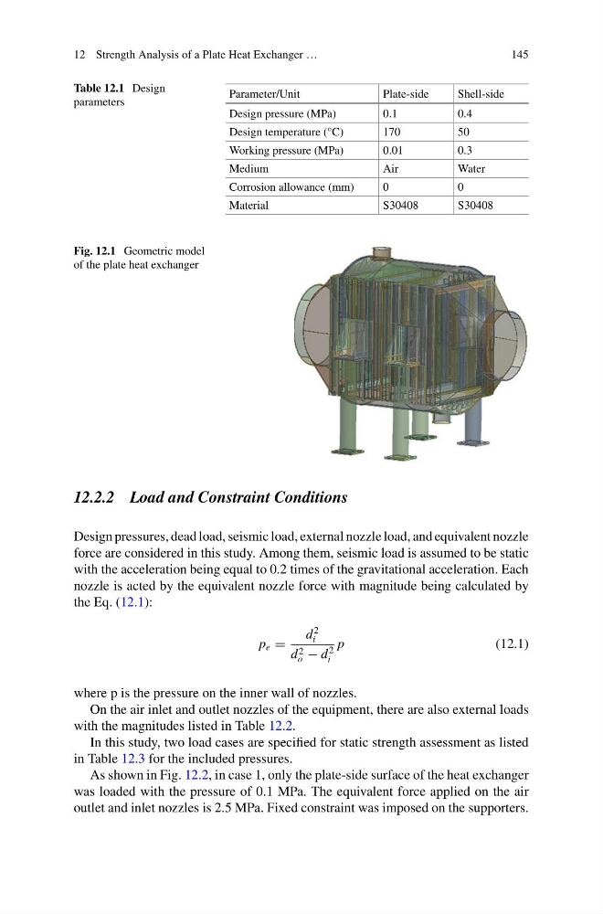
Fig. 12.1 Geometric model
of the plate heat exchanger
12.2.2 Load and Constraint Conditions
Design pressures, dead load, seismic load, external nozzle load, and equivalent nozzle
force are considered in this study. Among them, seismic load is assumed to be static
with the acceleration being equal to 0.2 times of the gravitational acceleration. Each
nozzle is acted by the equivalent nozzle force with magnitude being calculated by
the Eq. (12.1):
p e =
d
2
i
d 2
o − d
2
i
p
(12.1)
where p is the pressure on the inner wall of nozzles.
On the air inlet and outlet nozzles of the equipment, there are also external loads
with the magnitudes listed in Table 12.2.
In this study, two load cases are specified for static strength assessment as listed
in Table 12.3 for the included pressures.
As shown in Fig. 12.2, in case 1, only the plate-side surface of the heat exchanger
was loaded with the pressure of 0.1 MPa. The equivalent force applied on the air
outlet and inlet nozzles is 2.5 MPa. Fixed constraint was imposed on the supporters.
145
Table 12.1 Design
parameters
Parameter/Unit
Plate-side
Shell-side
Design pressure (MPa)
0.1
0.4
Design temperature (°C)
170
50
Working pressure (MPa)
0.01
0.3
Medium
Air
Water
Corrosion allowance (mm)
0
0
Material
S30408
S30408
Fig. 12.1 Geometric model
of the plate heat exchanger
12.2.2 Load and Constraint Conditions
Design pressures, dead load, seismic load, external nozzle load, and equivalent nozzle
force are considered in this study. Among them, seismic load is assumed to be static
with the acceleration being equal to 0.2 times of the gravitational acceleration. Each
nozzle is acted by the equivalent nozzle force with magnitude being calculated by
the Eq. (12.1):
p e =
d
2
i
d 2
o − d
2
i
p
(12.1)
where p is the pressure on the inner wall of nozzles.
On the air inlet and outlet nozzles of the equipment, there are also external loads
with the magnitudes listed in Table 12.2.
In this study, two load cases are specified for static strength assessment as listed
in Table 12.3 for the included pressures.
As shown in Fig. 12.2, in case 1, only the plate-side surface of the heat exchanger
was loaded with the pressure of 0.1 MPa. The equivalent force applied on the air
outlet and inlet nozzles is 2.5 MPa. Fixed constraint was imposed on the supporters.