

66
2 Description of the Wolfram SystemModeler
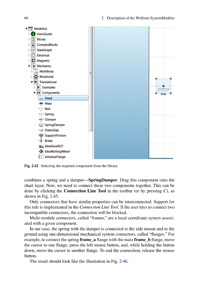
Fig. 2.42 Selecting the required component from the library
combines a spring and a damper—SpringDamper. Drag this component onto the
chart layer. Now, we need to connect these two components together. This can be
done by clicking the Connection Line Tool in the toolbar (or by pressing C), as
shown in Fig. 2.45.
Only connectors that have similar properties can be interconnected. Support for
this rule is implemented in the Connection Line Tool. If the user tries to connect two
incompatible connectors, the connection will be blocked.
Multi-module connectors, called “frames,” are a local coordinate system associated with a given component.
In our case, the spring with the damper is connected to the side mount and to the
ground using one-dimensional mechanical system connectors, called “flanges.” For
example, to connect the spring frame_a flange with the mass frame_b flange, move
the cursor to one flange, press the left mouse button, and, while holding the button
down, move the cursor to another flange. To end the connection, release the mouse
button.
The result should look like the illustration in Fig. 2.46.
2 Description of the Wolfram SystemModeler
Fig. 2.42 Selecting the required component from the library
combines a spring and a damper—SpringDamper. Drag this component onto the
chart layer. Now, we need to connect these two components together. This can be
done by clicking the Connection Line Tool in the toolbar (or by pressing C), as
shown in Fig. 2.45.
Only connectors that have similar properties can be interconnected. Support for
this rule is implemented in the Connection Line Tool. If the user tries to connect two
incompatible connectors, the connection will be blocked.
Multi-module connectors, called “frames,” are a local coordinate system associated with a given component.
In our case, the spring with the damper is connected to the side mount and to the
ground using one-dimensional mechanical system connectors, called “flanges.” For
example, to connect the spring frame_a flange with the mass frame_b flange, move
the cursor to one flange, press the left mouse button, and, while holding the button
down, move the cursor to another flange. To end the connection, release the mouse
button.
The result should look like the illustration in Fig. 2.46.