

6.3 Inverted Pendulum Problem
253
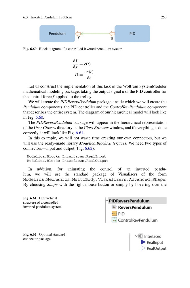
Fig. 6.60 Block diagram of a controlled inverted pendulum system
dI
dx
= e(t)
D =
de(t)
dt
Let us construct the implementation of this task in the Wolfram SystemModeler
mathematical modeling package, taking the output signal u of the PID controller for
the control force f applied to the trolley.
We will create the PIDReversPendulum package, inside which we will create the
Pendulum components, the PID controller and the ControlRevPendulum component
that describes the entire system. The diagram of our hierarchical model will look like
in Fig. 6.60.
The PIDReversPendulum package will appear in the hierarchical representation
of the User Classes directory in the Class Browser window, and if everything is done
correctly, it will look like Fig. 6.61.
In this example, we will not waste time creating our own connectors, but we
will use the ready-made library Modelica.Blocks.Interfaces. We need two types of
connectors—input and output (Fig. 6.62).
Modelica.Blocks.Interfaces.RealInput
Modelica.Blocks.Interfaces.RealOutput
In addition, for animating the control of an inverted pendulum, we will use the standard package of Visualizers of the form
Modelica.Mechanics.MultiBody.Visualizers.Advanced.Shape.
By choosing Shape with the right mouse button or simply by hovering over the
Fig. 6.61 Hierarchical
structure of a controlled
inverted pendulum system
Fig. 6.62 Optional standard
connector package
253
Fig. 6.60 Block diagram of a controlled inverted pendulum system
dI
dx
= e(t)
D =
de(t)
dt
Let us construct the implementation of this task in the Wolfram SystemModeler
mathematical modeling package, taking the output signal u of the PID controller for
the control force f applied to the trolley.
We will create the PIDReversPendulum package, inside which we will create the
Pendulum components, the PID controller and the ControlRevPendulum component
that describes the entire system. The diagram of our hierarchical model will look like
in Fig. 6.60.
The PIDReversPendulum package will appear in the hierarchical representation
of the User Classes directory in the Class Browser window, and if everything is done
correctly, it will look like Fig. 6.61.
In this example, we will not waste time creating our own connectors, but we
will use the ready-made library Modelica.Blocks.Interfaces. We need two types of
connectors—input and output (Fig. 6.62).
Modelica.Blocks.Interfaces.RealInput
Modelica.Blocks.Interfaces.RealOutput
In addition, for animating the control of an inverted pendulum, we will use the standard package of Visualizers of the form
Modelica.Mechanics.MultiBody.Visualizers.Advanced.Shape.
By choosing Shape with the right mouse button or simply by hovering over the
Fig. 6.61 Hierarchical
structure of a controlled
inverted pendulum system
Fig. 6.62 Optional standard
connector package