

240
6 Hierarchical Component Models
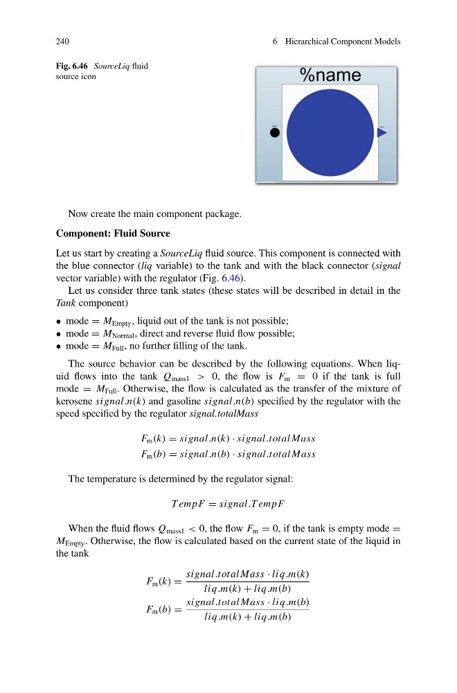
Fig. 6.46 SourceLiq fluid
source icon
Now create the main component package.
Component: Fluid Source
Let us start by creating a SourceLiq fluid source. This component is connected with
the blue connector (liq variable) to the tank and with the black connector (signal
vector variable) with the regulator (Fig. 6.46).
Let us consider three tank states (these states will be described in detail in the
Tank component)
• mode = M Empty , liquid out of the tank is not possible;
• mode = M Normal , direct and reverse fluid flow possible;
• mode = M Full , no further filling of the tank.
The source behavior can be described by the following equations. When liquid flows into the tank Q mass1 > 0, the flow is F m = 0 if the tank is full
mode = M Full . Otherwise, the flow is calculated as the transfer of the mixture of
kerosene signal.n(k) and gasoline signal.n(b) specified by the regulator with the
speed specified by the regulator signal.totalMass
F m (k) = signal.n(k) · signal.total Mass
F m (b) = signal.n(b) · signal.total Mass
The temperature is determined by the regulator signal:
T empF = signal.T empF
When the fluid flows Q mass1 < 0, the flow F m = 0, if the tank is empty mode =
M Empty . Otherwise, the flow is calculated based on the current state of the liquid in
the tank
F m (k) =
signal.total Mass · liq.m(k)
liq.m(k) + liq.m(b)
F m (b) =
signal.total Mass · liq.m(b)
liq.m(k) + liq.m(b)
6 Hierarchical Component Models
Fig. 6.46 SourceLiq fluid
source icon
Now create the main component package.
Component: Fluid Source
Let us start by creating a SourceLiq fluid source. This component is connected with
the blue connector (liq variable) to the tank and with the black connector (signal
vector variable) with the regulator (Fig. 6.46).
Let us consider three tank states (these states will be described in detail in the
Tank component)
• mode = M Empty , liquid out of the tank is not possible;
• mode = M Normal , direct and reverse fluid flow possible;
• mode = M Full , no further filling of the tank.
The source behavior can be described by the following equations. When liquid flows into the tank Q mass1 > 0, the flow is F m = 0 if the tank is full
mode = M Full . Otherwise, the flow is calculated as the transfer of the mixture of
kerosene signal.n(k) and gasoline signal.n(b) specified by the regulator with the
speed specified by the regulator signal.totalMass
F m (k) = signal.n(k) · signal.total Mass
F m (b) = signal.n(b) · signal.total Mass
The temperature is determined by the regulator signal:
T empF = signal.T empF
When the fluid flows Q mass1 < 0, the flow F m = 0, if the tank is empty mode =
M Empty . Otherwise, the flow is calculated based on the current state of the liquid in
the tank
F m (k) =
signal.total Mass · liq.m(k)
liq.m(k) + liq.m(b)
F m (b) =
signal.total Mass · liq.m(b)
liq.m(k) + liq.m(b)