

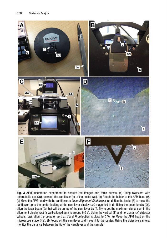
Fig. 3 AFM indentation experiment to acquire the images and force curves. (a) Using tweezers with
nonmetallic tips (tw), connect the cantilever (c) to the holder (hd). (b) Attach the holder to the AFM head (h).
(c) Move the AFM head with the cantilever to Laser Alignment Station (as). (c, d) Use the knobs (k) to move the
cantilever tip to the center looking at the cantilever display (cd, magnified in d). Using the beam knobs (bk),
align the laser beam (lb) that will be on top of the cantilever tip (t). Try to get the maximum signal sum in the
alignment display (ad) (a well-aligned sum is around 6.0 V). Using the vertical (V) and horizontal (H ) detector
wheels (dw), align the detector so that V and H deflection is close to 0 V). (e) Move the AFM head on the
microscope stage (ms). (f) Focus on the cantilever and move it to the center. Using the objective camera,
monitor the distance between the tip of the cantilever and the sample
358
Mateusz Majda
nonmetallic tips (tw), connect the cantilever (c) to the holder (hd). (b) Attach the holder to the AFM head (h).
(c) Move the AFM head with the cantilever to Laser Alignment Station (as). (c, d) Use the knobs (k) to move the
cantilever tip to the center looking at the cantilever display (cd, magnified in d). Using the beam knobs (bk),
align the laser beam (lb) that will be on top of the cantilever tip (t). Try to get the maximum signal sum in the
alignment display (ad) (a well-aligned sum is around 6.0 V). Using the vertical (V) and horizontal (H ) detector
wheels (dw), align the detector so that V and H deflection is close to 0 V). (e) Move the AFM head on the
microscope stage (ms). (f) Focus on the cantilever and move it to the center. Using the objective camera,
monitor the distance between the tip of the cantilever and the sample
358
Mateusz Majda