

70
B. S. Mukesh et al.
is shown in Fig. 5.6. In parabolic collector based systems, the flux concentrating on
to the receiver is not constant, the flux is distributed on the surface with a Gaussian
profile. The Gaussian flux distribution on the surface of the receiver is shown in
Fig. 5.6 having a spot diameter of 20 cm which is modeled in the ray tracing software,
TracePro. It is observed from Fig. 5.6 that the flux at the center of the receiver
surface is high and decreases with the increasing radius of spot. Here all the TracePro
simulations are done for average DNI of 641.1 W/m
2 for Jodhpur.
5.2.2 Receiver Design
As shown in Fig. 5.2, the receiver consists of a serpentine tube. The surface of the
receiver, which is exposed to concentrated solar irradiance, is 20 cm × 20 cm in
dimensions. Let, the outer diameter of pipe be D o = 10 mm. Thus, maximum of 20
parallel pipes can be fitted on receiver with surface area of 20 cm × 20 cm. However,
the direct contact of pipe must be avoided to allow flow development and heating up
with distance. Consequently, there must be a gap between these pipes. For n number
of parallel pipes there will be n − 1 number of gaps in the serpentine tube receiver
as in Fig. 5.2, let x is the size of gap between the pipes, y is the length of the parallel
pipes with uniform spacing. Therefore, the total length of receiver is given by:
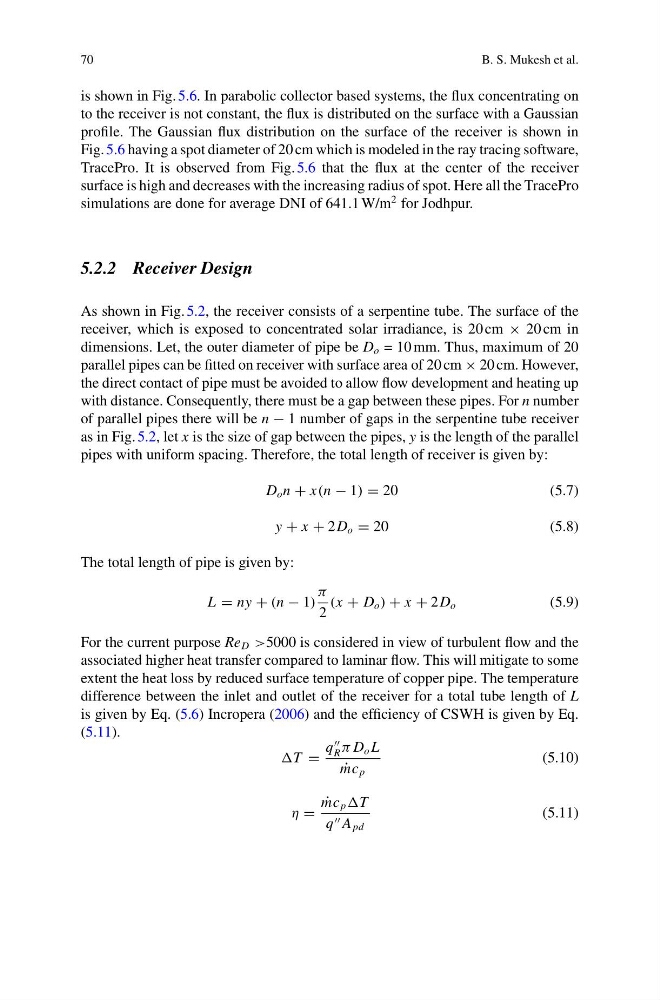
D o n + x(n − 1) = 20
(5.7)
y + x + 2D o = 20
(5.8)
The total length of pipe is given by:
L = ny + (n − 1)
π
2
(x + D o ) + x + 2D o
(5.9)
For the current purpose Re D >5000 is considered in view of turbulent flow and the
associated higher heat transfer compared to laminar flow. This will mitigate to some
extent the heat loss by reduced surface temperature of copper pipe. The temperature
difference between the inlet and outlet of the receiver for a total tube length of L
is given by Eq. (5.6) Incropera (2006) and the efficiency of CSWH is given by Eq.
(5.11).
T =
q
R π D o L
˙
mc p
(5.10)
η =
˙
mc p T
q A pd
(5.11)
B. S. Mukesh et al.
is shown in Fig. 5.6. In parabolic collector based systems, the flux concentrating on
to the receiver is not constant, the flux is distributed on the surface with a Gaussian
profile. The Gaussian flux distribution on the surface of the receiver is shown in
Fig. 5.6 having a spot diameter of 20 cm which is modeled in the ray tracing software,
TracePro. It is observed from Fig. 5.6 that the flux at the center of the receiver
surface is high and decreases with the increasing radius of spot. Here all the TracePro
simulations are done for average DNI of 641.1 W/m
2 for Jodhpur.
5.2.2 Receiver Design
As shown in Fig. 5.2, the receiver consists of a serpentine tube. The surface of the
receiver, which is exposed to concentrated solar irradiance, is 20 cm × 20 cm in
dimensions. Let, the outer diameter of pipe be D o = 10 mm. Thus, maximum of 20
parallel pipes can be fitted on receiver with surface area of 20 cm × 20 cm. However,
the direct contact of pipe must be avoided to allow flow development and heating up
with distance. Consequently, there must be a gap between these pipes. For n number
of parallel pipes there will be n − 1 number of gaps in the serpentine tube receiver
as in Fig. 5.2, let x is the size of gap between the pipes, y is the length of the parallel
pipes with uniform spacing. Therefore, the total length of receiver is given by:
D o n + x(n − 1) = 20
(5.7)
y + x + 2D o = 20
(5.8)
The total length of pipe is given by:
L = ny + (n − 1)
π
2
(x + D o ) + x + 2D o
(5.9)
For the current purpose Re D >5000 is considered in view of turbulent flow and the
associated higher heat transfer compared to laminar flow. This will mitigate to some
extent the heat loss by reduced surface temperature of copper pipe. The temperature
difference between the inlet and outlet of the receiver for a total tube length of L
is given by Eq. (5.6) Incropera (2006) and the efficiency of CSWH is given by Eq.
(5.11).
T =
q
R π D o L
˙
mc p
(5.10)
η =
˙
mc p T
q A pd
(5.11)