

8 Solar Thermal-Powered Adsorption Chiller
131
Hot water in
Hot water out
Chilled
water in
Chilled
water out
Cooling
water in
Cooling
water out
Bed 1
Bed 2
Condensate
return
Evaporator
Condenser
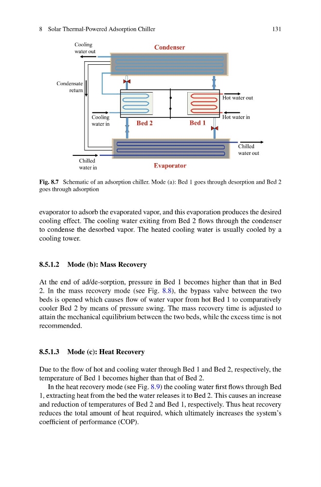
Fig. 8.7 Schematic of an adsorption chiller. Mode (a): Bed 1 goes through desorption and Bed 2
goes through adsorption
evaporator to adsorb the evaporated vapor, and this evaporation produces the desired
cooling effect. The cooling water exiting from Bed 2 flows through the condenser
to condense the desorbed vapor. The heated cooling water is usually cooled by a
cooling tower.
8.5.1.2 Mode (b): Mass Recovery
At the end of ad/de-sorption, pressure in Bed 1 becomes higher than that in Bed
2. In the mass recovery mode (see Fig. 8.8), the bypass valve between the two
beds is opened which causes flow of water vapor from hot Bed 1 to comparatively
cooler Bed 2 by means of pressure swing. The mass recovery time is adjusted to
attain the mechanical equilibrium between the two beds, while the excess time is not
recommended.
8.5.1.3 Mode (c): Heat Recovery
Due to the flow of hot and cooling water through Bed 1 and Bed 2, respectively, the
temperature of Bed 1 becomes higher than that of Bed 2.
In the heat recovery mode (see Fig. 8.9) the cooling water first flows through Bed
1, extracting heat from the bed the water releases it to Bed 2. This causes an increase
and reduction of temperatures of Bed 2 and Bed 1, respectively. Thus heat recovery
reduces the total amount of heat required, which ultimately increases the system’s
coefficient of performance (COP).
131
Hot water in
Hot water out
Chilled
water in
Chilled
water out
Cooling
water in
Cooling
water out
Bed 1
Bed 2
Condensate
return
Evaporator
Condenser
Fig. 8.7 Schematic of an adsorption chiller. Mode (a): Bed 1 goes through desorption and Bed 2
goes through adsorption
evaporator to adsorb the evaporated vapor, and this evaporation produces the desired
cooling effect. The cooling water exiting from Bed 2 flows through the condenser
to condense the desorbed vapor. The heated cooling water is usually cooled by a
cooling tower.
8.5.1.2 Mode (b): Mass Recovery
At the end of ad/de-sorption, pressure in Bed 1 becomes higher than that in Bed
2. In the mass recovery mode (see Fig. 8.8), the bypass valve between the two
beds is opened which causes flow of water vapor from hot Bed 1 to comparatively
cooler Bed 2 by means of pressure swing. The mass recovery time is adjusted to
attain the mechanical equilibrium between the two beds, while the excess time is not
recommended.
8.5.1.3 Mode (c): Heat Recovery
Due to the flow of hot and cooling water through Bed 1 and Bed 2, respectively, the
temperature of Bed 1 becomes higher than that of Bed 2.
In the heat recovery mode (see Fig. 8.9) the cooling water first flows through Bed
1, extracting heat from the bed the water releases it to Bed 2. This causes an increase
and reduction of temperatures of Bed 2 and Bed 1, respectively. Thus heat recovery
reduces the total amount of heat required, which ultimately increases the system’s
coefficient of performance (COP).